


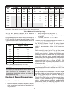
24
1
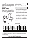
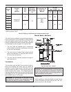
. Vent must terminate at least 4 ft below, 4 ft hori-
zontally from or 1 ft above any door, window or
g
ravity air inlet to the building.
2
. The vent must not be less than 7 ft above grade
when located adjacent to public walkways.
3. Terminate vent at least 3 ft above any forced air
inlet located within 10 ft.
4. Vent must terminate at least 4 ft horizontally, and
in no case above or below unless 4 ft horizontal
distance is maintained, from electric meters, gas
meters, regulators, and relief equipment.
5. Terminate vent at least 6 ft away from adjacent
walls.
6. DO NOT terminate vent closer than 5 ft below roof
overhang.
7. The vent terminal requires a 12 in. vent terminal
clearance from the wall.
8. Terminate vent at least 1 ft above grade, including
normal snow line.
9. Multiple direct vent installations require a 4 ft
clearance between the ends of vent caps located
on the same horizontal plane.
Canadian Installations
Refer to latest edition of the B149 Installation Code.
A vent shall not terminate:
1. Directly above a paved sidewalk or driveway
which is located between two single-family dwell-
ings and serves both dwellings.
2. Less than 7 ft (2.13 m) above a paved sidewalk or
paved driveway located on public property.
3. Within 6 ft (1.8 m) of a mechanical air supply inlet
to any building.
4. Above a meter/regulator assembly within 3 ft (915
mm) horizontally of the vertical centre-line of the
regulator.
5. Within 6 ft (1.8 m) of any gas service regulator
vent outlet.
6. Less than 1 ft (305 mm) above grade level.
7. Within 3 ft (915 mm) of a window or door which
can be opened in any building, any non-mechani-
cal air supply inlet to any building or the
combustion air inlet of any other appliance.
8. Underneath a verandah, porch or deck, unless the
verandah, porch or deck is fully open on a mini-
mum of two sides beneath the floor, and the
distance between the top of the vent termination
and the underside of the verandah, porch or deck
is greater than 1 ft (305 mm).
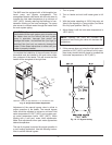
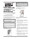
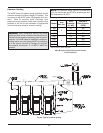
Venting Installation Tips
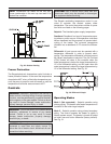
Support piping:
• horizontal runs—at least every 5 ft (1.5m)
• vertical runs—use braces
• under or near elbows
Venting Configurations
For heaters connected to gas vents or chimneys, vent
installations shall be in accordance with the NFGC
(U.S.), or B149 (Canada), or applicable provisions of
local building codes.
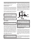
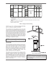
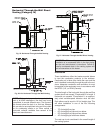
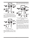
Vertical Venting (Category IV)
Installation
The maximum and minimum venting length for this
Category IV appliance shall be determined per the
NFGC (U.S.) or B149 (Canada).
The diameter of vent flue pipe should be sized accord-
ing to the NFGC (U.S.) and Appendix B of B149
(Canada). The minimum flue pipe diameter for con-
ventional venting using Category IV, stainless steel
WARNING: Examine the venting system at least
once a year. Check all joints and vent pipe
connections for tightness, corrosion or deterioration.
CAUTION: This venting system requires the
installation of a condensate drain in the vent piping
per the vent manufacturer’s instructions. Failure to
install a condensate drain in the venting system will
void all warranties on this heater.
WARNING: The Commonwealth of Massachusetts
requires that sidewall vented heaters, installed in
every dwelling, building or structure used in whole or
in part for residential purposes, be installed using
special provisions as outlined on page 55 of this
manual.