


43
2. FOR REFERENCE ONLY: Measure the blower
amp draw with the heater firing at 100% input and
compare the measured value to the values in
Table U. The amp draw is measured with a clamp-
on type amp probe clamped to the 14 AWG black
power wire going into the blower.
3. When firing at 100%, the desired heater combus-
tion CO2 is between 8.5 and 9.0% for natural gas
and 9.5 and 10.0% for propane with CO less than
100 ppm. If this combustion cannot be achieved
with the blower suction within the tolerances spec-
ified in Table T, contact the factory. The reference
amp draw reading may help to indicate if there is
a problem with the system or if blower adjustment
is required.
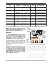
Manifold Check
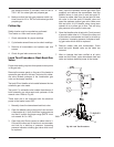
1. Check manifold gas pressure at the gas valve out-
let pressure tap (connection “D” in Fig. 47). This
pressure should read per the values in Table V for
natural and propane gas.
2. If the pressure reading differs by more than ± 0.2
in. WC, STOP – Call the factory for directions
on what to do next!
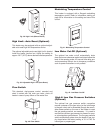
Safety Inspection
1. Check all thermostats and high limit settings.
2. During the following safety checks leave manome-
ters hooked up, check and record.
3. If other gas-fired appliances in the room are on the
same gas main, check all pressures on the MVB
with all other equipment running.
4. Check thermostats for ON-OFF operation.
5. Check high limits for ON-OFF operation.
6. While in operation, check flow switch operation.
7. Check the low gas pressure switch (if provided).
(For proper adjustment, use the attached
manometers, if available, to set pressure. The
scales on the switch are approximate only.) Low
CAUTION: Special manifold and air settings may
be required.
Finishing
1. Record all data on the “Start-up Checklist” located
at the back of this manual.
2. Disconnect the manometers and reconnect the
cap on the fan pressure switch tee and reinsert the
sealing screws into the bleedle valves.
3. Start-up is complete and the heater should be
operating properly.
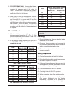
Model
Air Pressure
Setting (in. WC)
Setting
Tolerance
503 -2.3 ± 0.2 in. WC
753 -2.9 ± 0.2 in. WC
1003 -3.0 ± 0.2 in. WC
1253 -3.5 ± 0.2 in. WC
1503 -4.0 ± 0.2 in. WC
1753 -4.6 ± 0.2 in. WC
2003 -4.1 ± 0.2 in. WC
Table T: MVB Air Pressure Settings
Model Amp Draw
Setting
Tolerance
503 1.9 +0.0/-0.2
753 2.9 +0.0/-0.2
1003 4.8 +0.0/-0.2
1253 6.3 +0.0/-0.2
1503 8.1 +0.0/-0.2
1753 10.5 +0.0/-0.5
2003 13.0 +0.0/-0.5
Table U: MVB Amp Draw—Reference Information
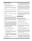
Model
Manifold Gas Pressure Setting
H
igh Fire Values (in. WC)
Natural Gas Propane Gas
503 -0.1 -0.1
7
53
-
0.4
-
0.1
1003 -0.8 -0.2
1253 -1.6 -0.2
1503 -2.4 -0.6
1753 -0.4 -0.1
2003 -1.0 -0.5
Table V: MVB Manifold Pressure Settings