


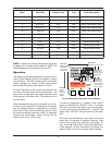
35
R
ank
I
tem Field
N
umber Field
T
ype
F
ault Description
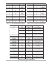
0 E
01
E
rr
E
rror
E
EPROM error
1 F
P
E
rr
W
arning
F
lame proof warning
2 BOIL OUT SHr Error Boiler outlet sensor short
3 BOIL OUT OPn Error Boiler outlet sensor open
4 BOIL IN SHr Error Boiler inlet sensor short
5 BOIL IN OPn Error Boiler inlet sensor open
6 SUP SHr Error System sensor short
7 SUP OPn Error System sensor open
8 OUTDR SHr Error Outdoor sensor short
9 OUTDR OPn Error Outdoor sensor open
10 DHW SHr Error DHW sensor short
11 DHW OPn Error DHW sensor open
Table R: Error Codes
WWSD - Selects the outdoor temperature that shuts
the heater off, no matter what the demand. NOTE: The
WWSD segment will be displayed on the LCD.
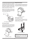
Operation
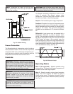
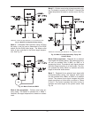
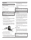
The Raypak modulating temperature control uses a
Liquid Crystal Display (LCD) as a method of supply-
ing information. The LCD is used to setup and monitor
system operation by means of three push buttons
(Item, ▲ and ▼) shown at the bottom of Fig. 36.
All items displayed by the control are organized into
two menus, the view menu and the adjust menu. The
active menu is displayed in the upper right hand side
of the display in the menu field. The default menu is
the view menu.
When the temperature control is powered up, the con-
trol turns on all segments in the display for 2 seconds,
then the software version is displayed for 2 seconds.
At the end of that 4 second period, the control enters
the normal operating mode and “VIEW” is displayed.
Pressing the scroll button “scrolls” through the dis-
played values in the “VIEW” menu.
To make an adjustment to a setting in the control,
begin by selecting the “ADJUST” menu. To change
from the view menu to the adjust menu, simultaneous-
ly press and hold all three buttons for 1 second. The
menu name, “ADJUST” will be displayed in the menu
field.
The menu will automatically revert back to the view
menu after 20 seconds of keyboard inactivity. Then
scroll to the desired item using the scroll button. Fi-
nally, use the ▲ or ▼ button to make the adjustment.
In the absence of other information, the values pro-
vided in Table Q should be used as default settings.
Modulating
Control
Item
DHW
Modulation
External Input
Signal
Offset
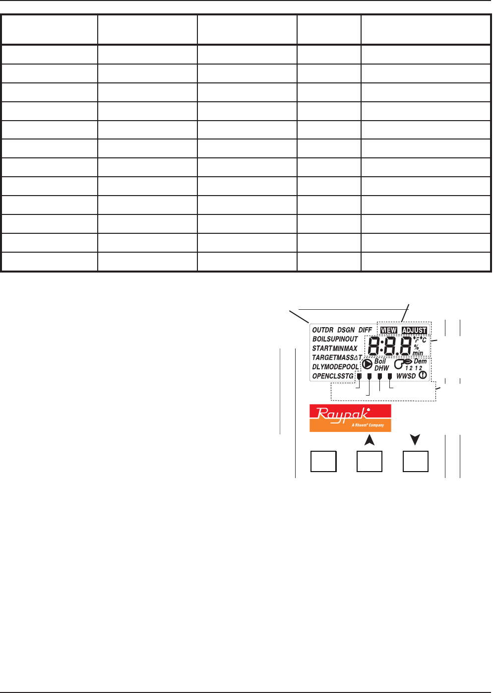
Fig. 36: Modulating Temperature Control Display
Item Field
Displays an
abbreviated
name of the
selected item
Buttons
Selects
Menus,
Items and
adjusts
settings
Menu Field
Displays the current menu
{
Number Field
Displays the
current value of
the selected
item
Status Field
Displays the
current status
of the control’s
inputs, outputs
and operation