


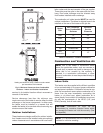
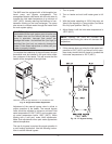

Relief Valve Piping
Temperature & Pressure Gauge
The temperature and pressure gauge is shipped loose
for field installation and must be installed within 12
inches of the boiler outlet (if possible) in an easily
readable location. Installation must comply with ASME
Section IV as well as all applicable national, state and
local codes.
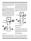
Hydrostatic Test
Unlike many types of heaters, this heater does not re-
quire hydrostatic testing prior to being placed in
operation. The heat exchanger has already been fac-
tory-tested and is rated for 160 psi operating pressure.
However, Raypak does recommend hydrostatic test-
ing of the piping connections to the heater and the rest
of the system prior to operation. This is particularly
true for hydronic systems using expensive glycol-
based anti-freeze. Raypak recommends conducting
the hydrostatic test before connecting gas piping or
electrical supply.
Leaks must be repaired at once to prevent damage to
the heater. NEVER use petroleum-based stop-leak
compounds.
To perform hydrostatic test:
1. Connect fill water supply. With bleed valve open,
fill heater with water. When water flows from bleed
valve, shut off water. Close bleed valve. Carefully
fill the rest of the system, making sure to eliminate
any entrapped air by using high-point vents. Close
13
feed valve. Test at standard operating pressure for
at least 24 hours.
2. Make sure constant gauge pressure has been
maintained throughout test.
3
. Check for leaks. Repair if found.
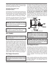
Cold Water Operation
This heater is equipped with a proprietary condensate
evaporation system which will evaporate any conden-
sate that may begin to accumulate inside the primary
heat exchanger with water temperatures as low as
120°F (49°C).
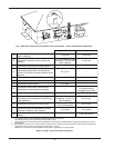
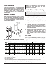
Heaters operated with an inlet temperature of less
than 120°F (49°C) MUST have a manual bypass (see
Fig. 16) or an approved low-temperature operation
system (Figs. 9 and 10) to prevent problems with con-
densation. This piping is similar to a
primary/secondary boiler installation with a bypass
acting as the secondary boiler piping. Raypak strong-
ly recommends that thermometer(s) be placed into the
heater piping next to the in/out header to facilitate tem-
perature adjustment. Inlet water temperatures below
120°F (49°C) can excessively cool the products of
combustion, resulting in collection of condensate in the
heat exchanger area beyond the capacity of the con-
densate evaporation system.
Failure to reach or exceed 120°F (49°C) within 7 min-
utes may damage or cause failure of the heat
exchanger, combustion chamber, or other parts within
the combustion chamber. It can cause operational
problems, bad combustion, sooting, flue gas leakage
and reduced service life of the appliance and the vent
system. A bypass allows part of the heater discharge
water to be mixed with the cooler water returning to the
heater inlet to increase the heater inlet temperature
above 120°F (49°C). This precautionary measure
should prevent the products of combustion from con-
densing beyond the ability of the condensate
management system employed in this heater in most
installations. Warranty claims will be denied for
damage or failures caused by condensation.
Cold water operation issues are applicable to both
cold water start and cold water run applications. Cold
water operation for 7 minutes or less on initial daily
start-up is acceptable. Where cold water starts will last
WARNING: Pressure relief valve discharge piping
must be piped near the floor and close to a drain to
eliminate the potential of severe burns. Do not pipe
to any area where freezing could occur. Refer to
local codes.
CAUTION: Damage due to internal condensation
may occur if the heater inlet water temperature does
not exceed 120°F (49°C) within 7 minutes of start-
up.
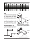
CAUTION: This heater requires forced water
circulation when the burner is operating. See Table F
and Table G for minimum and maximum flow rates
a
nd water pump selection. The pump must be
interlocked with the heater to prevent heater
operation without water circulation.
NOTE: Minimum pipe size for in/out connections is
2 in. NPT for 503 and 753 models and 2-
1
⁄2 in NPT for
1003–2003 models. Verify proper flow rates and ∆T
as instructed in this manual.