


38
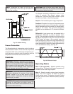
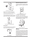
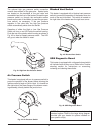
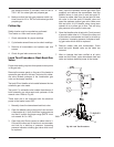
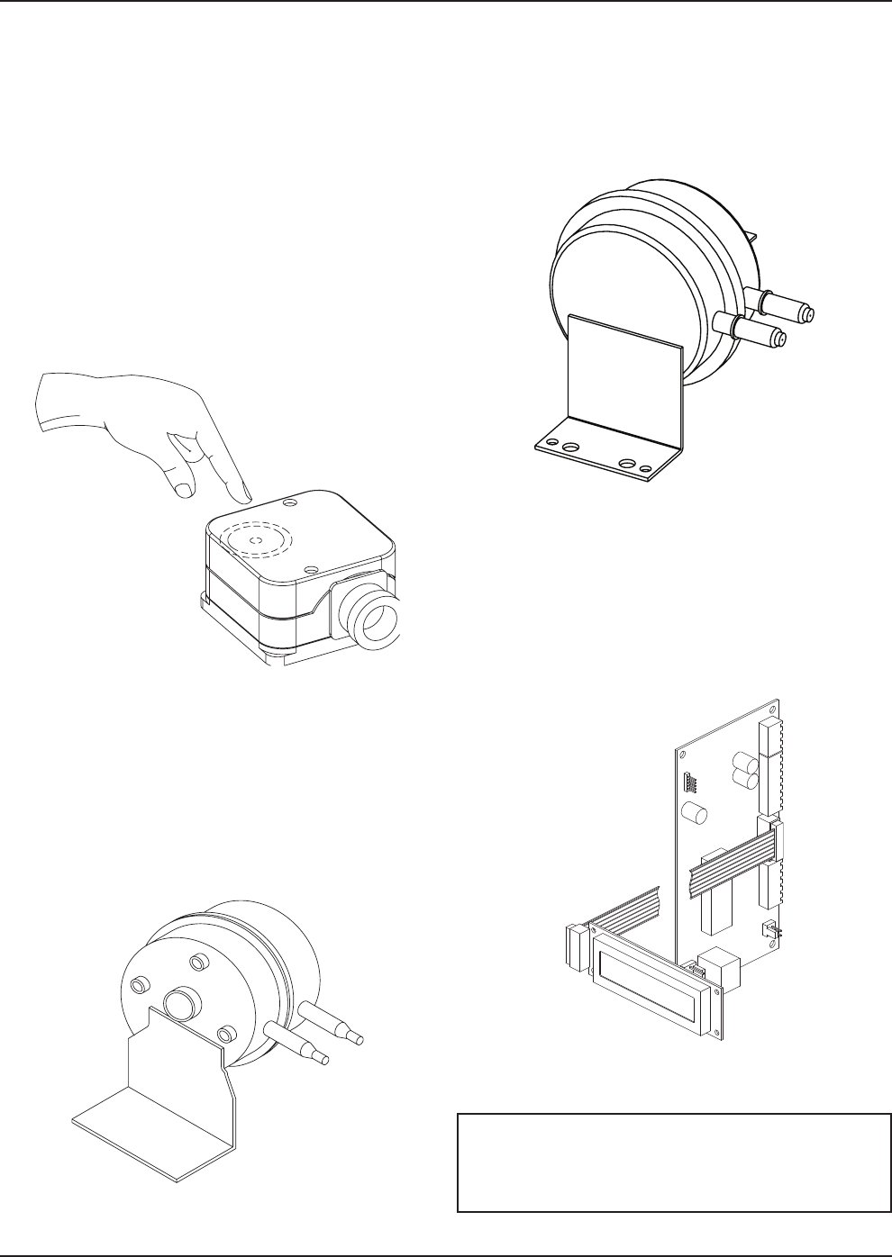
Fig. 43: High/Low Gas Pressure Switch
The optional high gas pressure switch connection
mounts down-stream of the gas valve. Special ports
are located on the backside of the gas valve and
accessible from the front of the heater (to reset the gas
pressure switch) or through the removable access
panels on the rear of the heater (to reset the gas pres-
sure switch), as necessary. If the gas pressure
regulator in the valve fails, the high gas pressure
switch automatically shuts down the burner.
Operation of either the High or Low Gas Pressure
Switch will turn on an LED inside the switch housing.
Push the top of the plastic switch housing as shown in
Fig. 43 to reset a tripped pressure switch. The LED
will go out when the switch is reset.
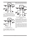
Air Pressure Switch
This heater is equipped with an air pressure switch to
prove the operation of the blower before allowing the
ignition control to begin a Call for Heat. It is located on
the right side of the lower flange of the blower mount-
ing assembly, directly behind the junction box.
Fig. 44: Air Pressure Switch
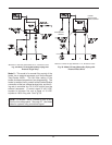
Blocked Vent Switch
This heater is equipped with a blocked vent pressure
switch to prevent the operation of the heater when too
much of the vent is blocked. This switch is located on
t
he right side of the heater near the right rear corner.
Fig. 45: Blocked Vent Switch
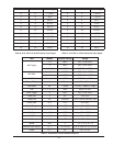
UDB Diagnostic Board
This heater is equipped with a diagnostic board which
will indicate faults as they occur. Refer to the Trouble-
shooting section for instructions on accessing,
reviewing and clearing these faults.
Fig. 46: UDB Diagnostic Board
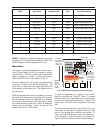
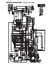
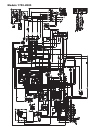
NOTE: The wiring diagrams in this manual show all
standard options. Refer to the large wiring diagram
provided with your heater for options installed on
your specific unit(s).