


29
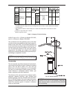
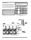
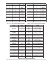
The total length of air supply pipe cannot exceed the
distances listed in Tables L and N. Each elbow used is
e
qual to 10 ft of straight pipe. This will allow installation
in any arrangement that does not exceed the lengths
shown in Tables L and N.
T
he vent cap is not considered in the overall length of
the venting system.
Care must be taken during assembly that all joints are
sealed properly and are airtight.
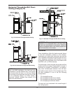
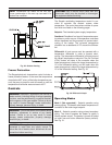
The vent must be installed to prevent the potential ac-
cumulation of condensate in the vent pipes. It is
required that:
1. The vent must be installed with a condensate
drain located in proximity to the heater as directed
by the vent manufacturer.
2. The vent must be installed with a slight upward
slope of not more than 1/4 inch per foot of hori-
zontal run to the vent terminal.
3. The vent must be insulated through the length of
the horizontal run.
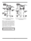
Termination
The vent cap MUST be mounted on the exterior of the
building. The vent cap cannot be installed in a well or
below grade. The vent cap must be installed at least 1
ft above ground level and above normal snow levels.
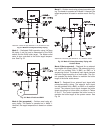
The vent cap MUST NOT be installed with any com-
bustion air inlet directly above a vent cap. This vertical
spacing would allow the flue products from the vent
cap to be pulled into the combustion air intake installed
above.
This type of installation can cause non-warrantable
problems with components and poor operation of the
heater due to the recirculation of flue products. Multi-
ple vent caps installed in the same horizontal plane
must have a 4 ft clearance from the side of one vent
cap to the side of the adjacent vent cap(s).
Combustion air supplied from outdoors must be free of
particulate and chemical contaminants. To avoid a
blocked flue condition, keep the vent cap clear of
snow, ice, leaves, debris, etc.
The stainless steel flue direct vent cap must be fur-
nished by the heater manufacturer in accordance with
i
ts listing (sales order option D-15).
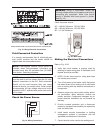
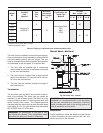
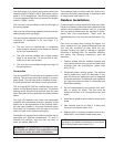
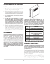
Outdoor Installation
Outdoor models must be vented with listed vent mate-
rial per the following instructions and installed with the
optional factory-supplied outdoor vent kit. A special
vent cap and air intake hood are provided in accor-
dance with CSA requirements. These must be
installed directly on the vent pipe as illustrated in Fig.
29.
Care must be taken when locating the heater out-
doors, because the flue gases discharged from the
vent cap can condense as they leave the cap.
Improper location can result in damage to adjacent
structures or building finish. For maximum efficiency
and safety, the following precautions must be
observed:
1. Outdoor models must be installed outdoors and
must use the outdoor vent cap and air intake hood
available from the manufacturer (sales order
option D-11).
2. Periodically check venting system. The heater’s
venting areas must never be obstructed in any
way and minimum clearances must be observed
to prevent restriction of combustion and ventilation
air. Keep area clear and free of combustible and
flammable materials.
3. Do not locate adjacent to any window, door, walk-
way, or gravity air intake. The vent must be
located a minimum of 4 ft horizontally from such
areas.
4. Install above grade level and above normal snow
levels.
5. Vent terminal must be at least 3 ft above any
forced air inlet located within 10 ft.
6. Adjacent brick or masonry surfaces must be pro-
tected with a rust-resistant sheet metal plate.
WARNING: No substitutions of flue pipe or vent
cap material are allowed. Such substitutions would
jeopardize the safety and health of inhabitants.
NOTE: The vent cap and air intake hood must be
furnished by the heater manufacturer in accordance
with its listing (sales order option D-11).