


123
FX-305
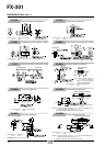
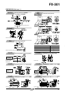
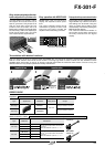
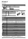
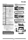
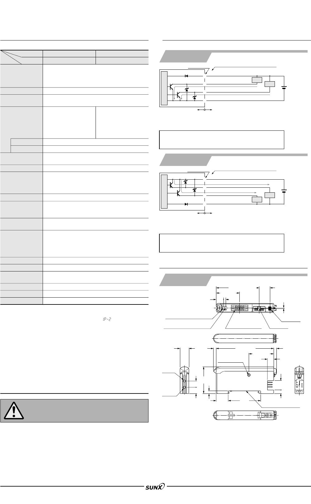
SPECIFICATIONS I/O CIRCUIT
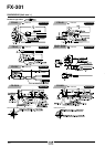
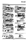
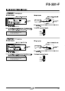
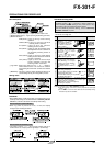
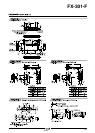
DIMENSIONS (Unit: mm in)
Amplifier
FX-305
FX-305P
2.5
0.098
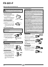
Digital display (Red)
Jog switch
MODE key
0.7
0.028
Output 1 operation indicator
(Orange)
Output 2 operation indicator
(Orange)
8.3
0.327
27.8 1.094
7 0.276
36.5
1.437
64.5 2.539
Communication
window
10.5 0.413
3.95
0.156
3.3 0.13
7 0.276
7 0.276
Beam-
emitting
part
Beam-
receiving
part
10
0.394
30
1.181
3
0.118
13.5
0.531
3
0.118
48.2 1.898
12
0.472
26.3 1.035
Suitable for 35 mm 1.378 in
width DIN rail
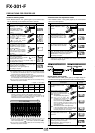
Notes: 1) The quick-connection sub cable does not have םV (brown) and 0 V (blue).
The power is supplied from the connector of the main cable.
2) 25 mA max., if five amplifiers, or more, are connected together.
Symbols … D: Reverse supply polarity protection diode
Z
D1, ZD2: Surge absorption zener diode
Tr
1, Tr2: NPN output transistor
Notes: 1) The quick-connection sub cable does not have םV (brown) and 0 V (blue).
The power is supplied from the connector of the main cable.
2) 25 mA max., if five amplifiers, or more, are connected together.
Symbols … D: Reverse supply polarity protection diode
Z
D1, ZD2: Surge absorption zener diode
Tr
1, Tr2: PNP output transistor
Color code of quick-connection cable
D
ZD1
Tr1
Tr2
50 mA max. (Note 2)
ZD2
D
ZD1
Tr1
Tr2
ZD2
1
3
4
2
1
3
4
2
Color code of quick-connection cable
Terminal No.
Terminal No.
NPN output type
PNP output type
FX-305P
FX-305
50 mA max. (Note 2)
Sensor circuit
Users’ circuitInternal circuit
Users’ circuitInternal circuit
50 mA max. (Note 2)
(Blue) 0 V (Note 1)
(Brown)
םV (Note 1)
(Black) Output 1
(White) Output 2
ם
מ
12 to 24 V DC
ע10 %
Load
Load
(Blue) 0 V (Note 1)
(Brown)
םV (Note 1)
(Black) Output 1
(White) Output 2
50 mA max. (Note 2)
Load
Load
ם
מ
12 to 24 V DC
ע10 %
Sensor circuit
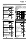
Type
NPN output
FX-305
PNP output
FX-305P
12 to 24 V DCע10 % Ripple P-P 10 % or less
Selectable either Light-ON or Dark-ON, with jog switch
Incorporated
4-digit red LED display
Incorporated
35 to 85 % RH, Storage: 35 to 85 % RH
Red LED (modulated)
Connector (Note 4)
Extension up to total 100 m 328.084 ft is possible with 0.3 mm
2
, or more, cable.
20 g approx.
Model No.
Item
Supply voltage
Power consumption
Response time
(Note 2)
Digital display
Sensitivity setting
Fine sensitivity adjustment function
Timer function
Automatic interference prevention
function (Note 2) (Note 3)
Ambient temperatu-
re
Ambient humidity
Emitting element
Material
Connecting method
Cable extension
Weight
Output operation
Short-circuit protection
Enclosure: Heat-resistant ABS, Transparent cover: Polycarbonate
Press switches: Acrylic, Jog switch: Heat-resistant ABS
Incorporated [Up to 4 sets of fiber heads can be mounted close together
(However, U-LG mode is 8 sets, H-SP mode is 2 sets.)]
H-SP: 65 !s or less, FAST 150 !s or less, STD: 250 !s or less, STDF: 700 !s or less,
LONG: 2.5 ms or less, U-LG: 4.5 ms or less selectable with jog switch
Incorporated with variable ON-delay / OFF-delay / ONE-SHOT / ON-delay⅐OFF-
delay / ON-delay⅐ONE-SHOT timer, switchable either effective or ineffective
(Timer period Output 1: 0.5 ms, 1 to 9999 ms, Output 2: 0.5 ms, 1 to 500 ms)
Normal operation: 960 mW or less (Current consumption 40 mA or less at 24 V supply voltage)
ECO mode: 600 mW or less (Current consumption 25 mA or less at 24 V supply voltage)
NPN open-collector transistor
•
Maximum sink current: each 50 mA (Note1)
• Applied voltage: 30 V DC or less
(between output and 0 V)
• Residual voltage: 1.5 V or less
[at each 50 mA (Note 1) sink current]
PNP open-collector transistor
•
Maximum source current: each 50 mA (Note1)
• Applied voltage: 30 V DC or less
(between output and
םV)
• Residual voltage: 1.5 V or less
[at each 50 mA (Note 1) source current]
Notes: 1)
2)
3)
4)
50 mA per output. 25 mA if five, or more, amplifiers are connected
in cascade.
When the interference prevention function ‘ ’ is set, the number
of mountable fibers becomes double. Furthermore, take care that
the response time also becomes double.
When the power supply is switched on, the light emission timing is
automatically set for interference prevention.
The cable for amplifier connection is not supplied as an accessory.
Make sure to use the optional quick-connection cables given below.
Main cable (4-core): CN-74-C1 (cable length 1 m 3.281 ft), CN-74-C2 (cable length 2 m 6.562 ft)
CN-74-C5 (cable length 5 m 16.404 ft)
Sub cable (2-core):
CN-72-C1 (cable length 1 m 3.281 ft), CN-72-C2 (cable length 2 m 6.562 ft)
CN-72-C5 (cable length 5 m 16.404 ft)
CN-73-C
□
and CN-71-C
□
cannot be used.
Thru-beam type (FT-B8): 1,700 (U-LG), 1,100 (LONG), 730 (STDF)
530 (STD), 400 (FAST), 200 (H-SP)
Reflective type (FD-B8): 600 (U-LG), 480 (LONG), 280 (STDF)
220 (STD), 160 (FAST), 85 (H-SP)
Normal mode: 2-level teaching / Limit teaching / Full-auto teaching /
Max. sensitivity teaching / Manual adjustment
Window comparator mode: Teaching (1-level / 2-level / 3-level) /
Manual adjustment
Sensing range
(mm)
מ10 to ם55 °C ם14 to ם131 °F
If 4 to 7 units are connected in cascade:
מ10 to ם50 °C ם14 to ם122 °F,
if 8 to 16 units are connected in cascade:
מ10 to ם45 °C ם14 to ם113 °F
(No dew condensation or icing allowed),
Storage:
מ20 to ם70 °C מ4 to ם158 °F
()
PRECAUTIONS FOR PROPER USE
This product is not a safety sensor. Its use is not intended or designed
to protect life and prevent body injury or property damage from
dangerous parts of machinery. It is a normal object detection sensor.
Output
(Output 1, Output 2)
All information is subject to change without prior notice.
08/2005