


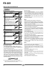
• Protect the amplifier from heat radiation or hot air.
• With the 350 ЊC 662 °F heat-resistant type fiber, the
surface of the fiber head or the spiral may be discolored
by heat. However, this does not affect its performance.
102
FX-301
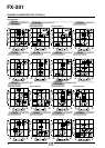
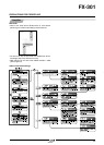
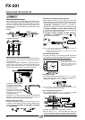
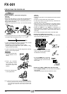
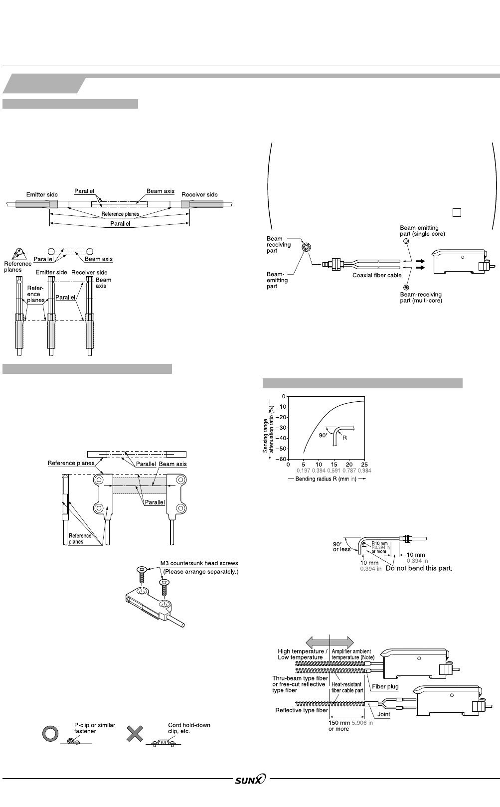
Connection with reflective coaxial type fiber
• With reflective coaxial type fiber, insert the center fiber
cable (single-core) into the beam-emitting inlet and the
outer fiber cable (multi-core) into the beam-receiving inlet.
FD-H35-M2 or FD-H20-M1 is marked ‘P’ on the beam-
emitting fiber cable and ‘D’ on the beam-receiving fiber cable.
FD-WG4, FD-WSG4 and FD-G4, FD-G6, FD-G6X are
composed of beam-emitting and beam-receiving fiber
cables that are different in diameter.
FD-G500, FD-EG1, FD-EG2, FD-EG3, FD-E22,
FD-H20-21 and FD-ENM1S1 are marked P on the
beam-emitting fiber cable.
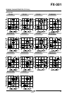
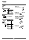
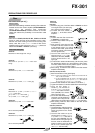
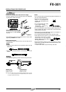
Fiber cable bending radius
•
If the fiber cable is bent at a smaller bending radius than allowable
bending radius, the sensing range decreases due to beam attenuation.
Fiber
Note: Please note that the 350 °C 662 °F
heat-resistant fibers, vacuum-
resistant and chemical-resistant
fibers cannot bend less than the
allowable bending radius.
Notes: 1) In case the fiber cables are not inserted to a position where they
stop, the sensing range reduces.
Notes: 2) Before connecting fiber cables to the amplifier, mount the fiber
attachments on their ends.
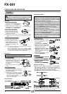
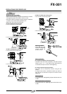
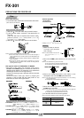
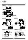
PRECAUTIONS FOR PROPER USE.
• Take care that, since the aperture angle of this product is very
narrow, the beam may not be received depending upon the setting.
At the time of installation, determine a reference plane, as shown in
the figure below, and taking sufficient care against beam
misalignment or tilt, install the emitting and receiving fibers so that
they are parallel.
<FT-K8>
Narrow beam type fiber mounting
•
Install the fiber using M3
countersunk head screws.
The tightening torque should
be 0.3 N⅐m or less.
Further, when using the fiber
at places having intense
vibrations, use a screw-
locking adhesive, etc.
• If mineral oil or solvent containing mineral oil component
adheres to the sensing surface, the lens may be
deformed. Take sufficient care to handle them.
• Take care that, since the aperture angle of this product is
very narrow, the beam may not be received depending
upon the setting.
At the time of installation, determine a reference plane, as
shown in the figure below, and taking sufficient care
against beam misalignment or tilt, install the beam-
emitting and receiving fibers so that they are parallel.
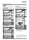
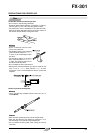
Thru-beam type wide beam fiber mounting
<FT-KV8 / FT-WKV8>
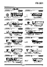
How to bend sleeve
• The bending radius must be R10 mm R0.394 in or more.
Please bend gradually using the fiber bender (FB-1) or a
round bar of "20 mm "0.787 in or more.
Note: Do not bend the sleeve of side-view type, narrow beam type, narrow-
view type and ultra-small diameter type fiber.
Method of fixing fiber cable
•
If fixing the fiber cable in position, make sure that it is set in
a manner as shown below, so that no load is applied on the
fiber. (Excluding FT-H35-M2, FT-H35-M2S6, FD-H35-M2
and FD-H35-M2S6)
For a allowable bending radius of 25 mm (0.984 in)
Use of heat-resistant type fiber
• Use by keeping 150 mm 5.906 in, or more, of the heat-
resistant fiber cable part at normal temperature.
08/2005