


522
FX-301-F
PRECAUTIONS FOR PROPER USE
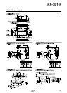
Mounting
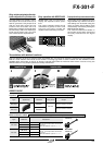
How to mount the amplifier
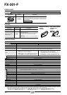
Cascading amplifiers
• Make sure that the power supply is off while cascading or
removing the amplifiers.
• Make sure to check the allowable ambient temperature, as it
depends on the number of amplifiers connected in cascade.
• In case two, or more, amplifiers are connected in cascade, make
sure to mount them on a DIN rail.
• When connecting in cascade, mount the amplifiers close to each
other, fitting them between the optional end plates (MS-DIN-E)
mounted at the two ends.
• When the amplifiers move on the DIN rail depending on the
attaching condition, fitting them between the optional end plates
(MS-DIN-E) mounted at the two ends.
• Up to maximum 15 amplifiers can be added (total 16 amplifiers
connected in cascade.)
• When connecting more than two amplifiers in cascade, use the
sub cable (CN-71-CⅪ) as the quick-connection cable for the
second amplifier onwards.
• Since the model setting gets changed if collective teaching is
done for the amplifiers in Leak setting (F7 mode) and in Liquid
setting (F9 mode) mounted in cascade, note that collective
teaching should not be done for amplifiers with different model
settings mounted in cascade.
• Since the communication function of this amplifier and that of
the fiber sensor FX-301/311 series is different, if these models
are mounted in cascade, do not use the communication
function.
• In case of cascading, wait for 10 minutes, or more, to use the
teaching function after the power is switched on.
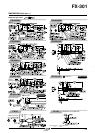
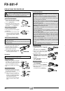
1
Mount the amplifiers, one by one,
on the 35 mm 1.378 in width DIN
rail.
(For details, refer to ‘Mounting’.)
2
Slide the sub units next to each
other, and connect the quick-
connection cables.
3
Mount the optional end plates
(MS-DIN-E) at both the ends to
hold the amplifiers between their
flat sides.
4
Tighten the screws to fix the end
plates (MS-DIN-E).
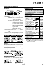
Cascading method
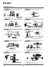
1
Loosen the screws of the end
plates (MS-DIN-E).
2
Remove the end plates (MS-DIN-E).
3
Slide the sub units and remove
them one by one.
(For details, refer to ‘Mounting’.)
Dismantling method
This product is not a safety sensor. Its use is not
intended or designed to protect life and prevent body
injury or property damage from dangerous parts of
machinery. It is a normal object detection sensor.
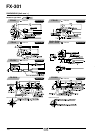
1
Fit the rear p
art o
f the mounting
section of the amplifier on a
35 mm
1.378 in
width DIN rail.
2
Press down the front part of the
mounting section of the amplifier on
the 35 mm 1.378 in width DIN rail.
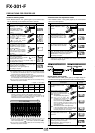
How to remove the amplifier
1
Push the amplifier forward.
2
Lift up the front part of the amplifier
to remove it.
Note:Take care that if the front part is lifted
up without pushing the amplifier
forward, the hook on the rear portion
of the mounting section is likely to
break.
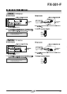
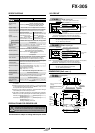
How to connect the fiber cables
• Make sure to fit the fiber attachment (FX-AT4), enclosed with
the fiber, to the fibers.
Please refer to the instruction manual of the fiber attachment for
the fitting method.
1
Snap the fiber lock lever down.
2
Insert the fiber cables slowly into
the inlets until they stop. (Note)
3
Return the fiber lock lever to the
original position, till it stops.
Note:In case the fiber cables are not
inserted to a position where they stop,
the sensing becomes unstable.
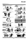
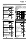
Connection
1
Holding the connector of the quick-
connection cable, align its projec-
tion with the groove at the top
portion of the amplifier connector.
2
Insert the connector till a click is
felt.
Connection method
1
Pressing the projection at the top of
the quick-connection cable connec-
tor, pull out the connector.
Note:Take care that if the connector is
pulled out without pressing the
projection, the projection may break.
Do not use a quick-connection cable
whose projection has broken.
Further, do not pull by holding the
cable, as this can cause a cable-
break.
Disconnection method
• Make sure that the power supply is off while connecting or
disconnecting the quick-connection cable.
08/2005