


96
FX-301
•
Make sure that the power supply is off while cascading or removing the amplifier.
•
Make sure to check the allowable ambient temperature, as it
depends on the number of amplifiers connected in cascade.
•
In case two, or more, amplifiers are connected in cascade,
make sure to mount them on a DIN rail.
•
When connecting in cascade, mount the amplifiers close to each other, fitting
them between the optional end plates (MS-DIN-E) mounted at the two ends.
• When the amplifiers move on the DIN rail depending on
the attaching condition, fitting them between the optional
end plates (MS-DIN-E) mounted at the two ends.
• Up to maximum 15 amplifiers can be added (total 16
amplifiers connected in cascade.)
• When connecting more than two amplifiers in cascade,
use the sub cable (CN-71-CⅪ) as the quick-connection
cable for the second amplifier onwards.
• Between the FX-301B(P)/G(P)/H(P) and the FX-301(P),
the setting status copy function via communication signal
cannot be used. If coupling these, please arrange
identical models one at a time.
PRECAUTIONS FOR PROPER USE
This product is not a safety sensor. Its use is not
intended or designed to protect life and prevent body
injury or property damage from dangerous parts of
machinery. It is a normal object detection sensor.
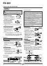
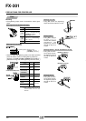
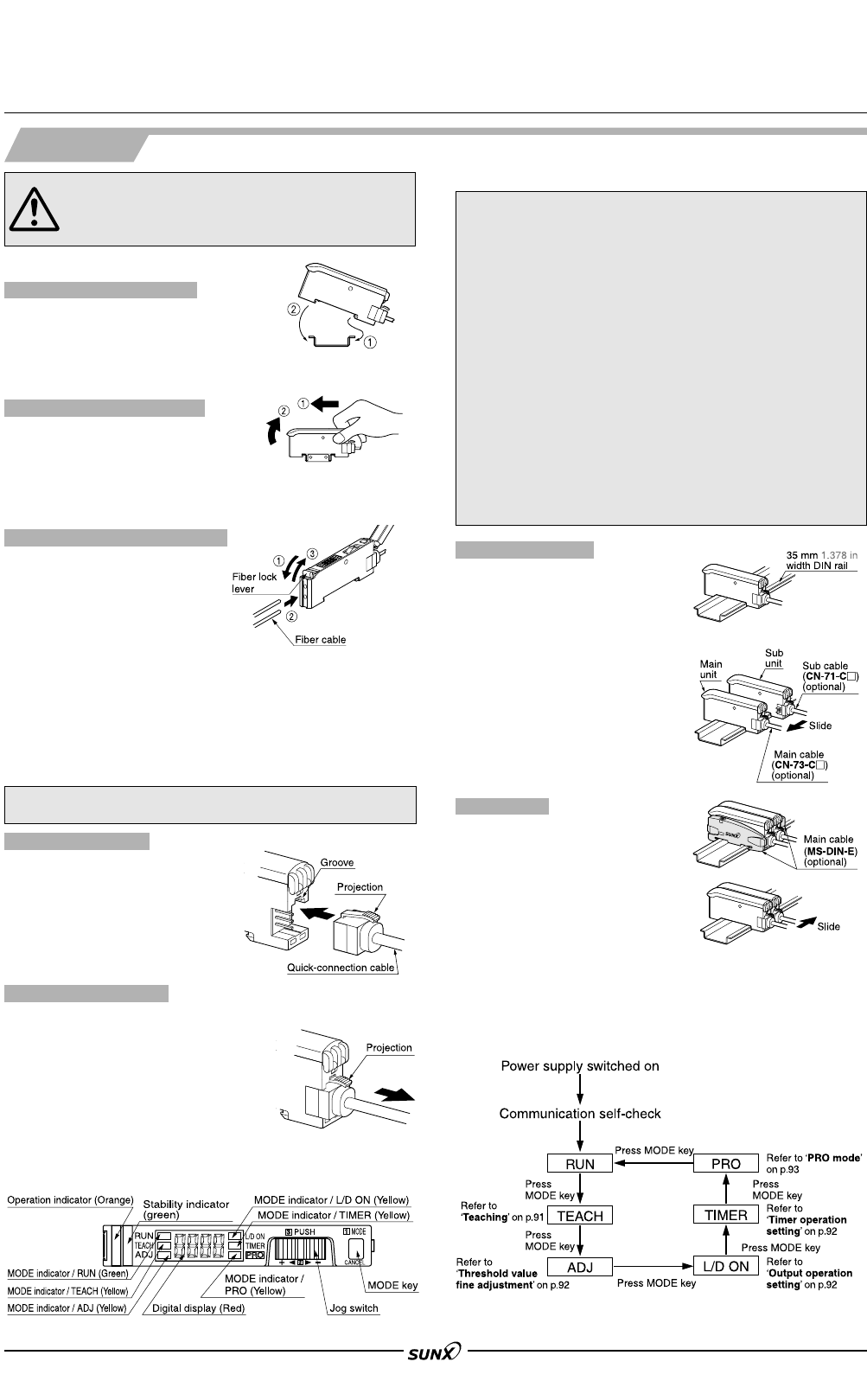
Mounting
1 Fit the rear part of the amplifier on
a 35 mm 1.378 in width DIN rail.
2
Press down the front part of the
mounting section of the amplifier on
the 35 mm 1.378 in width DIN rail.
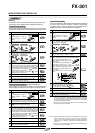
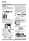
How to mount the amplifier
1 Mount the amplifiers, one by
one, on the 35 mm1.378 in
width DIN rail.
1
(For details, refer to ‘Mounting’.)
2
Slide the sub units next to the
main unit, and connect the
quick-connection cables.
3
Mount the optional end plates
(MS-DIN-E) at both the ends to
hold the amplifiers between
their flat sides.
4 Tighten the screws to fix the
end plates (MS-DIN-E).
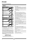
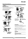
Cascading method
Connection
1 Holding the connector of the
quick-connection cable, align its
projection with the groove at
the top portion of the amplifier
connector.
2 Insert the connector till a click
is felt.
Connection method
1
Pressing the projection at the top of
the quick-connection cable connector,
pull out the connector.
Disconnection method
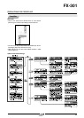
Cascading amplifiers
1 Push the amplifier forward.
2 Lift up the front part of the
amplifier to remove it.
Note:Take care that if the front part is lifted without pushing the amplifier
forward, the hook on the rear portion of the mounting section is likely to
break.
How to remove the amplifier
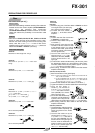
1
Snap the fiber lock lever down.
2
Insert fiber cables slowly into the
inlets until they stop. (Note 1)
3 Return the fiber lock lever
to the original position, till
it stops.
Notes: 1) In case the fiber cables are not inserted to a position where they
stop, the sensing range reduces.
Notes: 2) With the coaxial reflective type fiber, such as, FD-G4 or FD-FM2,
insert the single-core fiber cable into the beam-emitting inlet and
the multi-core fiber cable into the beam-receiving inlet. If they are
inserted in reverse, the sensing accuracy will deteriorate.
Note:
Take care that it the connector is pulled out
without pressing the projection, the projection
may break. Do not use a quick-connection
cable whose projection has broken.
Note:
Further, do not pull by holding the cable, as
this can cause a cable-break.
How to connect the fiber cables
Amplifier
35 mm 1.378 in width DIN rail
• Make sure that the power supply is off while connecting
or disconnecting the quick-connection cable.
Part description
1 Loosen the screws of the end
plates (MS-DIN-E).
2
Remove the end plates (MS-DIN-E).
3
Slide the sub units and remove
them one by one.
3
(For details, refer to ‘Mounting’.)
Dismantling
Operation procedure
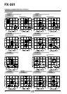
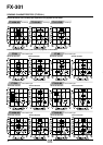
• When the power supply is switched on, communication
self-check is carried out and normal condition is
displayed [MODE indicator / RUN (green) lights up and
the digital display shows incident light intensity].
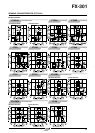
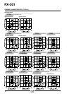
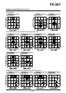
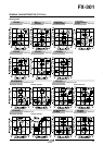
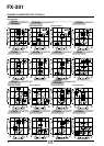
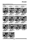
•
When MODE key is pressed, the mode changes as per the diagram below.
When jog switch is pressed, the setting is confirmed.
When MODE key is pressed for 2 sec., or more, the sensor returns to the RUN mode.
Cancellation is possible by pressing MODE key during setting.
1 Loosen the screws of the end
plates (MS-DIN-E).
2
Remove the end plates (MS-DIN-E).
3
Slide the sub units and remove
them one by one.
3
(For details, refer to ‘Mounting’.)
08/2005