


520
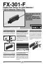
FX-301-F
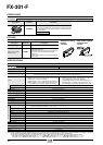
ORDER GUIDE
FD-F7 series, FT-F9 series
12 to 24 V DC
ע10 % Ripple P-P 10 % or less
Normal operation: 960 mW or less (Current consumption 40 mA or less at 24 V supply voltage)
ECO mode: 600 mW or less (Current consumption 25 mA or less at 24 V supply voltage)
NPN open-collector transistor
• Maximum sink current: 100 mA (50 mA, if five, or more,
amplifiers are connected in cascade.)
•
Applied voltage: 30 V DC or less (between output and 0 V)
•
Residual voltage: 1.5 V or less [at 100 mA (50 mA, if five, or
more, amplifiers are connected in cascade.) sink current]
Leak setting (F7 mode): OFF with detection of leak, Liquid setting (F9 mode):Using the jog switch, choose the signal OFF condition between absence of liquid and presence of liquid.
Incorporated
250!s or less (Note 1)
Individual teaching / Collective teaching
Orange LED (lights up when the output is ON)
Green LED [lights up during liquid setting (F9 mode)]
RUN: Green LED, TEACH ⅐ ALL ⅐ ADJ ⅐ DISP ⅐ OUT:Yellow LED
4 digit red LED display
Incorporated
Delay timer [used only for liquid setting (F9 mode)] (Timer setting selectable from 10 ms, 100 ms, 1,000 ms, and none)
0 to
ם50 ЊC ם32 toם122 ЊF (If 8 to 16 units are connected in cascade: 0 toם45 ЊC ם32 toם113 ЊF
(No dew condensation), Storage:
מ20 toם70 ЊC מ4 toם158 ЊF
35 to 85 % RH, Storage: 35 to 85 % RH
Sunlight: 10,000 ?x at the light-receiving face, Incandescent light: 3,000 ?x at the light-receiving face
EN 50081-2, EN 50082-2, EN 60947-5-2
1,000 V AC for one min. between all supply terminals connected together and enclosure (Note 2)
20 MΩ, or more, with 250 V DC megger between all supply terminals connected together and enclosure (Note 2)
10 to 150 Hz frequency, 0.75 mm 0.030 in amplitude in X, Y and Z directions for two hours each
98 m/s
2
acceleration (10 G approx.) in X, Y and Z directions for five times each
Red LED (modulated)
Enclosure: Heat-resistant ABS, Case cover: Polycarbonate, Switch: Acrylic
Connector (Note 3)
Extension up to total 100 m 328.084 ft is possible with 0.3 mm
2
, or more, cable.
20 g approx.
PNP open-collector transistor
• Maximum source current: 100 mA (50 mA, if five, or
more, amplifiers are connected in cascade.)
•
Applied voltage: 30 V DC or less (between output and םV)
•
Residual voltage: 1.5 V or less [at 100 mA (50 mA, if five, or
more, amplifiers are connected in cascade.) source current]
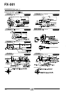
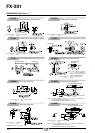
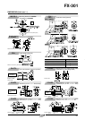
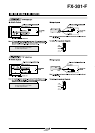
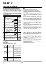
OPTIONS
End plates
Appearance Model No. Description
MS-DIN-E
When cascading multiple amplifiers, or when it moves depending
on the way it is installed on a DIN rail, these end plates ensure
that all amplifiers are mounted together in a secure and fully
connected manner.
Amplifier mounting
bracket
• MS-DIN-2
Fiber sensor amplifier
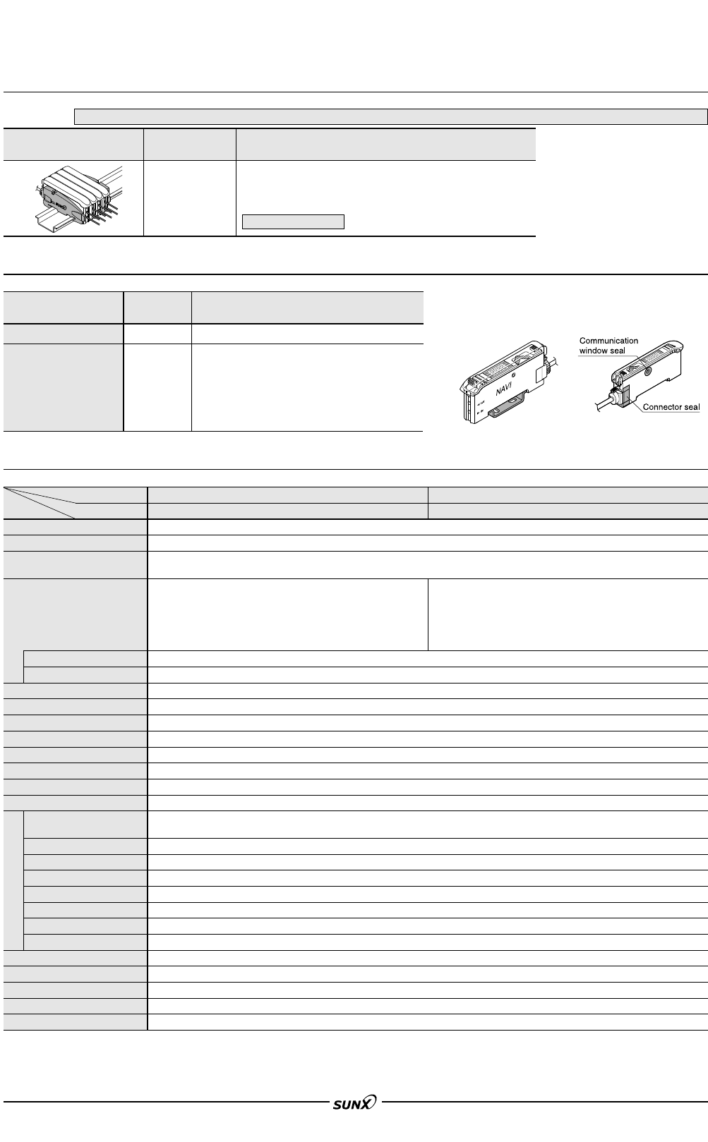
protection seal
• FX-MB1
Designation Model No. Description
MS-DIN-2
Mounting bracket for amplifier
Amplifier mounting bracket
FX-MB1
10 sets of 2 communication window seals and 1 connector seal
Communication window seal:
It prevents malfunction due to transmission signal from another
amplifier, as well as, prevents effect on another amplifier.
Connector seal:
It prevents contact of any metal, etc., with the pins of the quick-
connection cable.
Fiber sensor amplifier
protection seal
FX-301-F
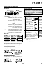
Applicable fibers
Supply voltage
Power consumption
Output
Output operation
Short-circuit protection
Response time
Sensitivity setting
Operation indicator
Model indicator
MODE indicator
Digital display
Fine sensitivity adjustment function
Timer function
Ambient temperature
Ambient humidity
Ambient illuminance
EMC
Voltage withstandability
Insulation resistance
Vibration resistance
Shock resistance
Emitting element
Material
Connecting method
Cable extension
Weight
Item
Model No.
NPN output
FX-301P-F
PNP outputType
SPECIFICATIONS
Environmental resistance
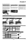
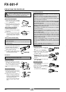
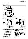
Notes: 1)
When detecting leak (output OFF) during leak setting (F7 mode), since the sensor flashes the emitted light, only the response action for turning the signal back to ON is delayed (1 sec. approx.).
Notes: 2) The voltage withstandability and the insulation resistance values given in the above table are for the amplifier only.
Notes: 3) The cable for amplifier connection is not supplied as an accessory. Make sure to use the optional quick-connection cable given below.
Main cable (3-core): CN-73-C1 (cable length 1 m 3.281 ft), CN-73-C2 (cable length 2 m 6.562 ft), CN-73-C5 (cable length 5 m 16.404 ft)
Sub cable (1-core): CN-71-C1 (cable length 1m 3.281 ft), CN-71-C2 (cable length 2 m 6.562 ft), CN-71-C5 (cable length 5 m 16.404 ft)
End plates are not supplied with the amplifier. Please order it separately when the amplifiers are mounted in cascade.
Two pcs. per set
08/2005