


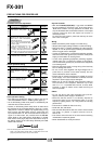
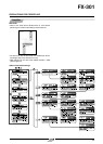
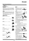
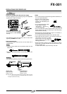
<FX-AT10, FX-AT13>
1
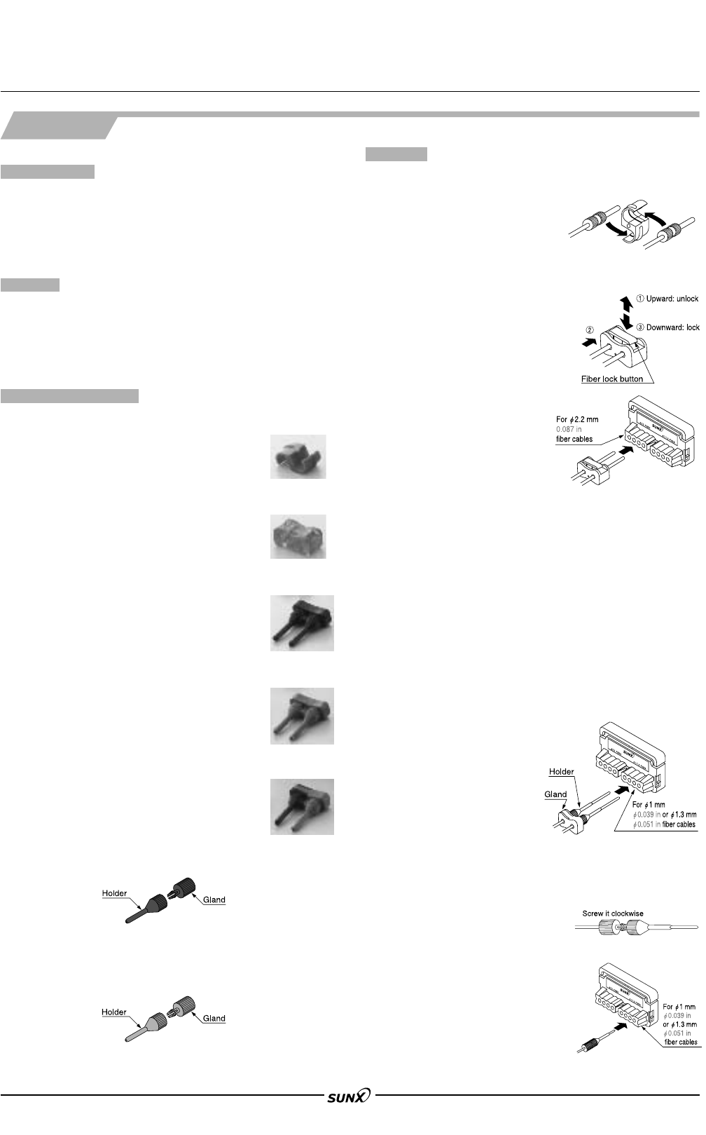
Thread the fiber
cable
through the
gland and holder separately, and
screw the gland into the holder
clockwise.
2
Insert the fiber cables one by one
into the holes for
"
1.0 mm
"
0.039 in
or
"
1.3 mm
"
0.051 in fiber cable of
the fiber cutter (FX-CT2) from the
direction shown in the figure right. (At
this time, insert the attachment to a
position at which it stops. The fibers
will be cut at a position approx. 0.5
mm 0.020 in from the holder.)
103
FX-301
Fiber
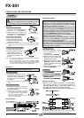
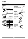
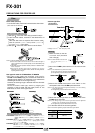
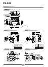
PRECAUTIONS FOR PROPER USE
.
•
When the beam-emitting and beam-receiving fiber cables are
inserted into the fiber sensor amplifier (FX-301/302/303/311
series etc.), the enclosed fiber attachment
(FX-AT2/AT3/AT4/AT5/AT6) facilitates insertion of the fiber
cables and reduces the possibility of incorrect fiber cable
insertion.
Product outline
Mounting
•
Take care that FX-AT2, FX-AT3, FX-AT4, FX-AT5 and FX-AT6
cannot be used with fiber sensor amplifiers having a pitch,
between the beam-emitting and the beam-receiving fiber
cables, other than 7 mm 0.276 in. In case of fiber sensor
amplifiers having a pitch other than 7 mm 0.276 in, please use
attachments FX-AT10 or FX-AT13. (accessory)
Cautions
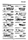
Component description
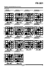
Fiber attachments (FX-ATⅪ)
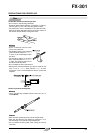
<FX-AT2>
Attachment for fixed-length fiber: orange
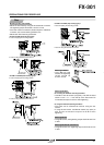
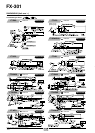
<FX-AT2>
1
Mount the plug part of the fiber cables in FX-AT2, as shown
in the figure below. (The resin plug
has a groove to hold it in place.)
2 Connect the fiber cables, in
condition 1, to the fiber sensor
amplifier.
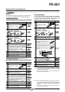
<FX-AT3>
1 Confirm that the fiber lock button
of FX-AT3 is in unlock side.
2 Insert the fiber cables one by one,
in condition 1.
3
After inserting, press down the fiber
lock button. The fiber cables are fixed
at the desired position. (In order to
unlock the fiber cables, press the fiber
lock button towards unlock direction
from the opposite side.)
4
Insert the fiber cables into the
holes for
"
2.2 mm
"
0.087 in fiber
cables of the fiber cutter (FX-CT2)
from the direction shown in the
figure right.
<FX-AT3>
Attachment for
"
2.2 mm
"
0.087 in fiber: clear
orange
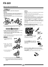
<FX-AT4>
Attachment for
"
1 mm
"
0.039 in fiber: black
<FX-AT5>
Attachment for
"
1.3 mm
"
0.051 in fiber: gray
<FX-AT6>
Attachment for
"
1 mm /
"
1.3 mm
"
0.039 in /
"
0.051 in mixed fiber
for
"
1 mm
"
0.039 in fiber: black,
for
"
1.3 mm
"
0.051 in fiber: gray
<FX-AT10>
Attachment for
"
1 mm
"
0.039 in fiber: black
This is enclosed by FX-AT4.
<FX-AT13>
Attachment for
"
1.3 mm
"
0.051 in fiber: gray
This is enclosed by FX-AT5.
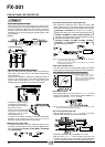
5
Cut both fiber cables simultaneously. (At this time, place
the attachment without any gap against the fiber cutter.
The fiber cables will be cut at a position approx. 10.5 mm
0.413 in from the tip of the fiber cable.)
6 After cutting, connect the fiber cables to the fiber sensor
amplifier immediately.
<FX-AT4, FX-AT5, FX-AT6>
1 Mount the holders on the gland lightly.
Notes: 1) If both long holders and short holders are enclosed with the
fiber, use the short holders.
1 Notes: 2) In case of FX-AT6, match the colors of the holders and the
gland.The black color is for
"
1.0 mm
"
0.039 in fiber cable and
the gray color is for
"
1.3 mm
"
0.051 in fiber cable.
2 Insert the fiber cables into the holders, in condition 1.
3
Tighten the holders to fix the fiber cables at the desired length.
4
Insert the fiber cables, in
condition
3
, into the holes for
"
1.0 mm
"
0.039 in or
"
1.3 mm
"
0.051 in fiber cables of the fiber
cutter (FX-CT2) from direction
shown in the figure right.
5
Cut both fiber cables simultaneously.
(At this time, insert the attachment to
a position at which it stops. The fiber
cables will be cut at a position approx. 0.5 mm 0.020 in from the holder.)
6 After cutting, insert the fiber cables to the fiber sensor
amplifier immediately.
()
08/2005