


104
FX-301
Fiber
PRECAUTIONS FOR PROPER USE
.
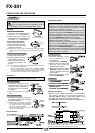
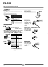
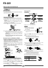
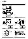
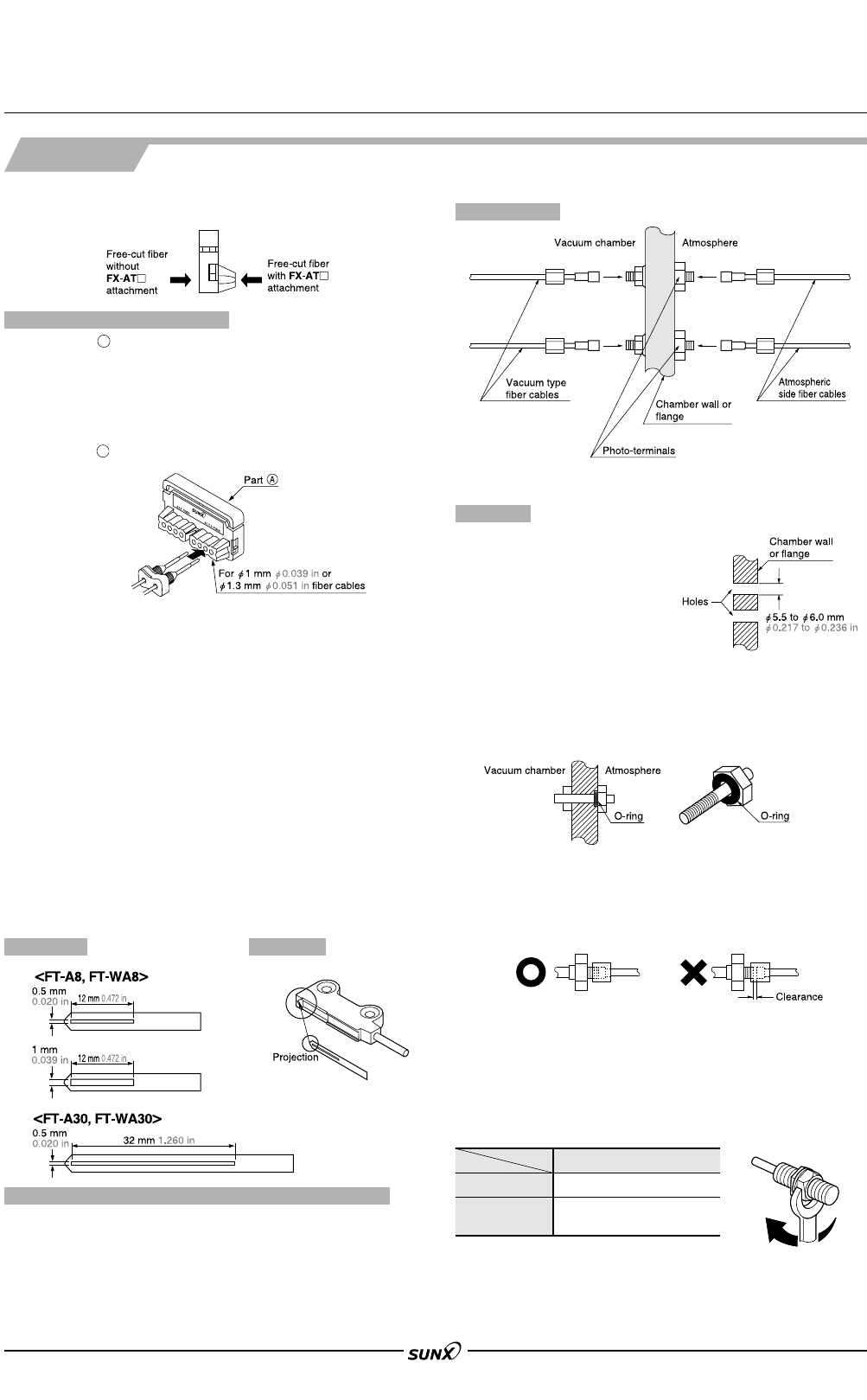
Fiber cutter (FX-CT2)
•
To cut the fiber cables, insert them from the direction shown below.
(Fiber cable insertion direction)
1 Slide part of the fiber cutter fully upward till it stops.
2 Insert the fiber cables, mounted in the attachment, till
they stop.
Take care that there are separate fiber insertion cable
holes for
"
2.2 mm
"
0.087 in and
"
1.0 mm
"
0.039 in or
"
1.3 mm
"
0.051 in fiber cables.
3 Slide part of the fiber cutter down to cut the fibers.
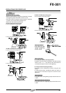
Notes: 1) The fiber cables should be cut in one stroke.
Notes: 2) Once a fiber cable is cut off at a hole, do not use the hole again. If
used, it degrades the cut surface quality and the detectability may
deteriorate.
Notes: 3) The blade cannot be replaced. Please purchase an additional fiber
cutter, if required.
Notes: 4) Note that the sensing range may be reduced by up to 20 %
depending on the cut condition. Hence, decide the setting distance
by taking sufficient margin.
How to use fiber cutter (FX-CT2)
()
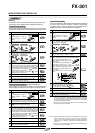
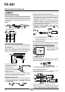
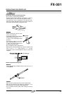
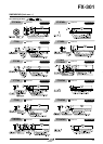
Seal type slit mask for FT-WA30/A30, FT-WA8/A8
• Two types of slit masks are enclosed. (one type for
FT-A30 and FT-WA30) Apply the enclosed slit mask when
detecting small objects or as measures not to saturate the
emitted light amount for short-range sensing.
However, the sensing range is reduced when the slit mask
is mounted.
As the slit mask is seal type, stick it by aligning the
projection of the slit mask with the upper portion of the
fiber head, as shown in the figure below.
Sensing range when mounting slit mask [with FX-301(P)]
Mounting
Slit masks
FT-WA30/A30: 2,500 mm 98.425 in (LONG) / 1,000 mm 39.370 in
(STD) / 600 mm 23.622 in (FAST) / 200 mm 7.874 in
(S-D)
FT-WA8/A8:
400 mm 15.748 in (LONG) / 200 mm 7.874 in (STD) / 140 mm
5.512 in (FAST) / 70 mm 2.756 in (S-D) (0.5ן12 mm
0.020ן0.472 in slit mask)
FT-WA8/A8: 800 mm 31.496 in (LONG) / 400 mm 15.748 in (STD) /
280 mm 11.024 in (FAST) / 140 mm 5.512 in (S-D)
(
1ן12 mm
0.039ן0.472 in
slit mask)
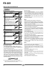
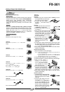
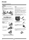
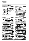
Vacuum type fiber
Leakage: 1.33ן10
–10
Pa⅐m
3
/sec. [He] or less
1 Make two holes on the vac-
uum tank wall (chamber
wall or flange).
Note:The hole diameter must be from
"5.5 to "6.0 mm "0.217 to
"0.236 in.
2 Mount the FV-BR1 photo-terminal on the vacuum tank
wall.
Notes: 1) The attached O-ring must be mounted.
Notes: 2) The O-ring must be used at the atmospheric side.
Notes: 3) The tightening torque should be 0.58 N⅐m or less.
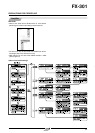
3 Mount the FT-J6 atmospheric side fibers on the
atmospheric side of the FV-BR1 photo-terminals.
Notes: 1) The fixing nuts must be tightened securely. If not, the sensing
range may decrease.
Notes: 2) The tightening torque should be 0.58 N⅐m or less.
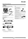
4 Mount the vacuum type fibers on the vacuum side of the
FV-BR1 photo-terminals.
Notes: 1) The fixings rings of the vacuum type fibers must be tightened
securely. If not, the sensing range may decrease.
Notes: 2) The tightening torque should be 0.58 N⅐m or less.
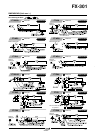
5 Fix the fiber head of the vacuum type fiber.
Note:The maximum tightening torque should be as given below.
Tightening torque
0.29 N⅐m
0.58 N⅐m
M2.6
M4
M6
Configuration
Mounting
A
A
08/2005