


38
to remove any dirt and lint that may have ac-
cumulated in the compartment or on the blower
and motor. Dirt and lint can create excessive
loads on the motor resulting in higher than
normal operating temperatures and shortened
service life.
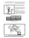
Heat Exchanger and Burner Maintenance
The furnace should operate for many years
without excessive soot buildup in the fl ue pas-
sageways, however, the fl ue passageways,
the vent system, and the burners should be
inspected and cleaned (if required) by a quali-
fi ed serviceman annually to ensure continued
safe operation. Particular attention must be
given to identify deterioration from corrosion or
other sources.
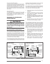
SYSTEM OPERATION
INFORMATION
Proper maintenance is most important to achieve
the best performance from a furnace. Follow
these instructions for years of safe, trouble free
operation.
• Do not place combustible materials on or
against the furnace cabinet or the vent
pipe.
• Do not store gasoline or any other fl am-
mable vapors and liquids in the vicinity of
the furnace.
• Change or replace the air fi lters monthly
during any period when the circulating
blower is operating regularly.
• Always replace the doors on the furnace
after servicing. Do not operate the furnace
without all doors and covers in place.
• Avoid operating the furnace when win-
dows and doors are open.
• Be sure that the thermostat is properly
installed and is not being affected by drafts
or heat from lamps or other appliances.
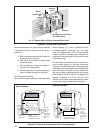
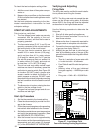
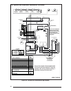
Sequence of Operation
Operating sequences for the heating, cooling,
and fan modes are described below. Refer to
the wiring diagrams (Figures 29) and the voltage
fi eld wiring diagram (Figure 26).
Heating Mode:
1. On a call for heat the thermostat closes,
applying 24 VAC to the W terminal on the
control board.
2. The control board checks for continuity on
the 24 VAC limit control circuit (over-tempera-
ture limit switch, fl ame rollout switches and
blocked vent switch in series). If an open limit
is detected the control board will energize
the inducer and the conditioned air blower.
All other system functions will be inoperable
until the limit circuit closes. While the limit
is open, the red LED will pulse at a rate of
1 blink per unit time.
3. The furnace control checks for continuity
across the pressure switch (24 VAC). If the
pressure switch is closed the heat mode
sequence will not continue. If it remains
closed for 10 seconds the red LED will blink
3 times repetitively until the fault condition
clears.
4. The inducer is energized.
5. The pressure switch will close. If the pres-
sure switch does not close after 10 seconds
the fault LED will blink 2 times repetitively
and the inducer will continue to run until the
switch is closed.
6. The inducer will pre-purge for 30 seconds
and then the igniter will start its warm-up as
follows:
Initial Power up: After 30 seconds of igniter
warm-up the gas valve (24 VAC) will then
open. The igniter circuit will stay energized
for 3 seconds after the gas valve opens.
After Initial Power up: The control has a
programmed adaptive ignition feature which
varies the warm-up period as follows: If igni-
tion is successful the warm-up is reduced
by 3-seconds on each subsequent call for
heat until ignition failure occurs. Upon igni-
tion failure, the warm-up is increased by
3-seconds on the next try. If successful, the
timing remains fi xed at this level. In general,
whenever ignition failure occurs the warm-up
interval is increased by 3-seconds on the
next try. And if successful, it remains there.
Minimum and maximum warm-up time limits
are set at 6 and 54-seconds, respectively.
7. The furnace control must prove fl ame via
the fl ame the fl ame sensor 5 seconds after
the gas valve opens. If fl ame is sensed, all
burners are on and the igniter cools off. If
no fl ame is sensed, the gas valve closes im-
mediately and the inducer continues to run.