


12
NOTE: To avoid condensate freezing in the drain
trap assembly and tubing, insulate around
the drain trap assembly and all tubing located
in unconditioned space.
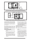
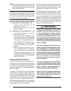
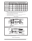
NOTE: When converting the furnace, to horizontal
left, ensure that the drainage port on the in-line
drain assembly is downward as shown in Figure
4. If the in-line drain assembly is not rotated, then
the furnace may not drain properly.
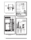
SUPPLY AIR PLENUM INSTALLATION
A. Installation on a concrete slab - *RL
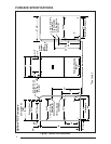
1. Construct a hole in the fl oor per the
dimensions in Figure 5.
2. Place the plenum and the furnace as
shown in Figure 6.
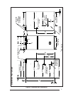
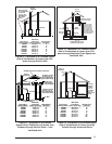
B. Installation on a combustible fl oor - *RL
1. Cut hole and frame the hole per the
dimensions in Figure 7.
2. Place sub-base for combustible fl oors
over the hole with its duct collar extended
downward. Attach the supply air plenum
to the base in a manner which will as-
sure 1” clearance to the fl ooring or other
combustible material. Place furnace
on the combutsible base as shown in
Figure 8.
3. When the furnace is installed on a fac-
tory or site-built cased air conditioning
coil, the sub-base is not necessary.
However, the plenum attached to the
coil casing must be installed such that its
surfaces are at least 1” from combustible
material in Figure 9.
CIRCULATING AIR SUPPLY
Plenums and air ducts must be installed in ac-
cordance with the Standard for the Installation of
Air Conditioning and Ventilating Systems (NFPA
No. 90A) or the Standard for the Installation of
Warm Air Heating and Air Conditioning Systems
(NFPA No. 90B).
If outside air is utilized as return air to the furnace
for ventilation or to improve indoor air quality, the
system must be designed so that the return air to
the furnace is not less than 50°F (10°C) during
heating operation. If a combination of indoor and
outdoor air is used, the ducts and damper system
must be designed so that the return air supply to
the furnace is equal to the return air supply under
normal, indoor return air applications.
When a cooling system is installed which uses the
furnace blower to provide airfl ow over the indoor
coil, the coil must be installed downstream (on the
outlet side) or in parallel with the furnace.
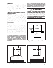
If a cooling system is installed in parallel with the
furnace, a damper must be installed to prevent
chilled air from entering the furnace and condens-
ing on the heat exchanger. If a manually operated
damper is installed, it must be designed so that
operation of the furnace is prevented when the
damper is in the cooling position and operation
of the cooling system is prevented when the
damper is in the heating position.
!
WARNING:
Products of combustion must not be
allowed to enter the return air ductwork
or the circulating air supply. Failure
to prevent products of combustion
from being circulated into the living
space can create potentially hazardous
conditions including carbon monoxide
poisoning that could result in personal
injury or death.
All return ductwork must be secured
to the furnace with sheet metal screws.
For installations in confi ned spaces,
all return ductwork must be adequately
sealed and joints must be taped. When
return air is provided through the bot-
tom of the furnace, the joint between
the furnace and the return air plenum
must be sealed.
The fl oor or platform on which the fur-
nace is mounted must provide sound
physical support of the furnace with no
gaps, cracks, or sagging between the
furnace and the fl oor or platform.
Return air and circulating air ductwork
must not be connected to any other
heat producing device such as a fi re-
place insert, stove, etc.