


32
To check the heat anticipator setting either:
1. Add the current draw of the system compo-
nents; or
2. Measure the current fl ow on the thermostat
R-W circuit after the circulating blower motor
has started.
Set the heat anticipator according to the ther-
mostat manufacturer’s instructions for heat
anticipator settings.
START-UP AND ADJUSTMENTS
Prior to start-up, verify that:
1. The line voltage power leads are securely
connected, that the polarity of the con-
nections is correct, and that the furnace is
properly grounded.
2. The thermostat wires (R, W, Y, and G) are
securely connected to the correct leads on
the terminal strip of the circuit board.
3. The gas line service pressure does not
exceed 10.0 in. water column (0.36 psig),
and is not less than 4.5 in. water column
(0.16 psig) for natural gas. For LP gas the
line service pressure must not exceed 14
in. water column (0.51 psig), and must not
be less than 11.0 in. W.C. (0.40 psig).
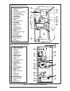
4. The roll-out and vent safety manual reset
switches are closed. If necessary, press the
red button to reset a switch. See Figure 30
for location. DO NOT install a jumper wire
across a switch to defeat its function. If a
switch reopens on start-up, DO NOT reset
the switch without identifying and correcting
the fault condition which caused the switch
to trip.
5. The blower door is in place, closing the door
switch in the line voltage circuit.
6. The gas line has been purged and all con-
nections are leak tight.
Start-Up Procedure
1. Set the thermostat to the lowest setting.
2. Close the disconnect(s) to provide line volt-
age to the furnace.
3. Follow the procedures given on the operating
instructions label attached to the furnace.
4. Set the thermostat above room temperature
and verify the sequence of operation. (See
the SEQUENCE OF OPERATION.)
5. After the furnace has run for approximately
fi ve minutes, set the thermostat below room
temperature and verify steps (9) through
(11) of the SEQUENCE OF OPERATION.
Verifying and Adjusting
Firing Rate
The fi ring rate must be verifi ed for each installa-
tion to prevent over-fi ring the furnace.
NOTE: The fi ring rate must not exceed the rate
shown on the furnace rating plate. At altitudes
above 2000 ft. the fi ring rate must be adjusted
as described in the high altitude section.
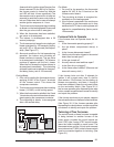
Use the following procedure to determine the
fi ring rate:
1. Shut off all other gas fi red appliances.
2. Start the furnace and allow it to run for at
least three minutes.
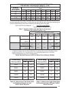
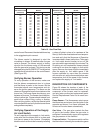
3. Measure the time (in seconds) required for
the gas meter to complete one revolution.
4. Convert the time per revolution to cubic feet
of gas per hour using Table 13.
5. Multiply the gas fl ow rate in cubic feet per
hour by the heating value of the gas in Btu
per cubic foot to obtain the fi ring rate in Btuh.
Example:
• Time for 1 revolution of a gas meter with
a 1 cubic foot dial = 40 seconds.
• From Table 9 read 90 cubic feet per hour
of gas.
• Heating value of the gas (obtained
from gas supplier) = 1040 Btu per cubic
foot.
• Firing rate = 1040 x 90 = 93,600 Btuh.
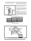
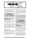
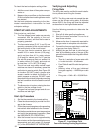
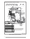
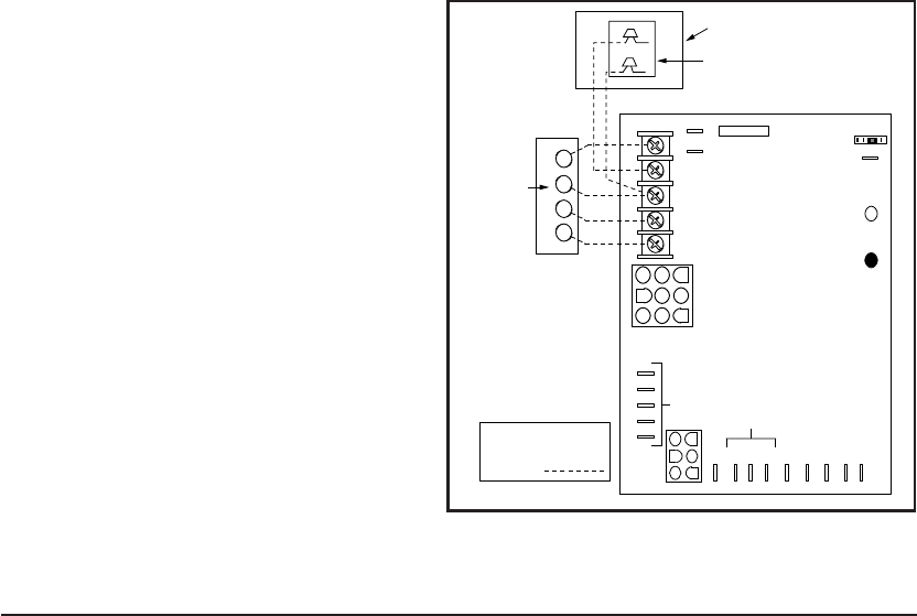
Figure 27. Low Voltage Field,
Four-wire Heating/Cooling Applications
R C Y G W
A/C Condensing Unit
Condensing Unit
Control Box
Room
Thermostat
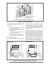
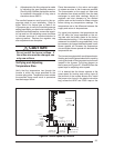
Flame Signal Light
(Yellow)
Status Light
(Red)
60
90
120
180
Blower Off
Timing
TWIN
3 Amp
Fuse
COM
24 V
HUM
Neutrals
Low Voltage
Connections
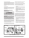
41
52
63
7
8
9
4
5
6
1
2
3
EAC
HUM
M1
M2
M3
HEAT
L1
XFMR
Unused Motor Leads
EAC
R Y G W
Connect
R & W
For
Heating
Only
FIELD WIRING
NOTE: The "Y"
terminal on the
UTEC control board
must be connected
to the thermostat
for proper cooling
mode operation.
COOL