


27
Concentric Vent Termination
Concentric vent termination kits are approved for
use with these furnaces. The kit part numbers
are 904176 (3 inch) and 904177 (2 inch). For
proper installation of the concentric vent termina-
tion, follow the installation instructions provided
with that kit.
Side Wall Vent Kit
This side wall vent kit is approved for use with
these furnaces. The kit part number is 904347,
and instructions for proper installation are pro-
vided with that kit.
DRAINAGE OF CONDENSATE
FROM FURNACE
!
WARNING:
The condensate produced by the fur-
nace must be drained. Do not connect
a water supply to the drainage hose of
the furnace.
NOTE: The condensate drain should be protected
from freezing when in unheated spaces.
The condensate drainage system is internal to
the furnace. It is not recommended to connect
additional traps to the exterior of the furnace. Do-
ing so will have adverse effects on the operation
of the furnace. The drain may exit either the right
or left side of the furnace cabinet.
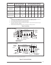
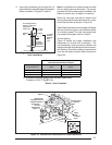
The condensate drain can be routed to a fl ow drain
or to a condensate pump. Ensure that the drain
maintains a downward slope from the unit to the
drain. Refer to Figure 24 for more details.
For a right side drain simply extend the tubing out
of the 7/8” hole in the cabinet, see Figure 21. For
a left side drain follow the steps below:
1. Loosen the clamp on the soft exit tube (see
Figure 24.)
2. Rotate the soft exit tube (counter clockwise,
180° upfl ow *RC models; clockwise 90°
downfl ow *RL models.)
3. Re-tighten the clamp. MAKE SURE CLAMP
IS TIGHT TO AVOID LEAKAGE OF CON-
DENSATE.
4. Route the tubing out of the 7/8” hole located
8 inches up from the bottom furnace.
The condensate should drain from the plastic
collector box (location A in Figure 24) as droplets
or a small stream. If you notice the furnace has
operated for more than 5 minutes without drain-
ing or the red status light on the control board is
pulsing a 2-blink code follow the steps below.
1. Remove the collector box soft tube at loca-
tion A in Figure 24 and insure the exit from
the collector box is clear of any debris or
obstructions.
2. Replace this tube and insure the fi t to the
header spout is air tight. Air will be drawn into
the header if this connection is not tight.
3. Check other tube connections along the
drain system. Insure that all are air tight.
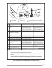
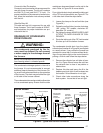
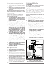
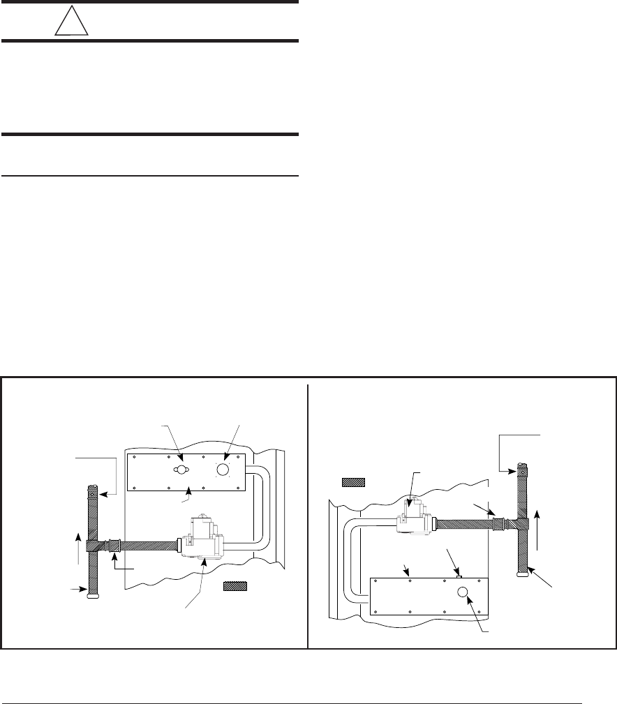
Some Utilities
Require Shut-
Off Valve to
be 4 to 5 feet
Above Floor
Denotes field-
provided and
installed
components.
Shut-Off Valve
with
1/
8" NPT
Plugged Tap
Burner Viewport
Roll-Out Limit
Automatic Gas Valve
(with manual shut-off)
Burner
Assembly
Ground
Joint
Union
Dripleg
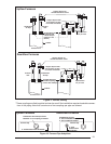
Figure 25. Typical Gas Service Connection
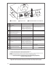
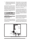
Some Utilities
Require Shut-
Off Valve to
be 4 to 5 feet
Above Floor
Denotes field-
provided and
installed
components.
Shut-Off Valve
with
1/
8" NPT
Plugged Tap
Burner Viewport
Automatic
Gas Valve
(with manual
shut-off)
Burner
Assembly
Ground Joint
Union
Roll-Out Limit
Dripleg
Upfl ow Models Downfl ow Models