


25
Outside
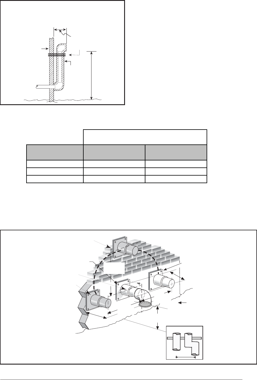
Wall
Support
Vent Configuration to
Provide 12" Minimum
height above
Snow Level.
1/2"
Armaflex
Insulation or
Equivalent
(If Required)
12" Above
Normally
Expected
Snow
Level
12" Min.
19" Max.
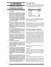
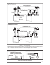
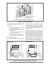
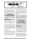
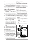
4. Insure the combustion air inlet pipe (for a 2
pipe installation) has a 90 degree termination
elbow as shown in Figures 21 and 22.
Figure 21. Alternate Horizontal
Vent Installation
Note: A combustion air intake must be provided
with an elbow opening downward. The screen
provided with the furnace must be installed in the
elbow to prevent entry of debris or creatures.
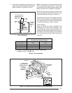
When the vent pipe must exit an exterior wall
close to the grade or expected snow level, a riser
should be provided as shown in Figure 20.
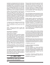
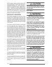
Table 6 describes the maximum length of fl ue pipe
that can travel through an unconditioned space
or an exterior space. The total vent length must
not exceed the lengths noted on Table 5.
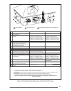
Vertical Venting
Figure 23 shows the proper installation and
clearances for vertical vent termination. The
roof penetration must be properly fl ashed and
waterproofed with a plumbing roof boot or equiva-
lent fl ashing. Termination spacing requirements
from the roof and from each other must be per
Figure 23.
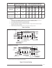
36" max.
18" min.
Exhaust Vent
Option B
Exhaust Vent
Option A
Exhaust Vent
Option C
Mounting Kit
Faceplate Secured
to Wall with Screws
18" Min.
36" Max.
7" Min.
8" Min.
12" Min. to
Normal Snow Level
Combustion
Air Inlet
Grade
Level
or Normal
Snow
Inlet
Exhaust
18" Min.
36" Max.
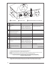
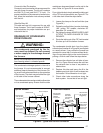
Figure 22. Exhaust and Combustion Air Pipe Clearances
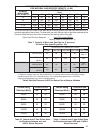
Table 6. Vent Protection
20 45 70
020 70
-20 10 60
Winter Design
Termperature (°F)
Without Insulation
(feet)
With Insulation
(feet) ‡
Maximum Flue Pipe Length in
Unconditioned and Exterior Spaces
‡ = Insulation thickness greater than 3/8 inch, based on an
R value of 3.5 (ft*°F*hr)/(BTU*in)