


17
The size and other criteria for these openings
must be per the following sections.
Combustion air openings must not be restricted
in any manner.
Furnaces installed in a confi ned space which
supply circulating air to areas outside of the
space must draw return air from outside the
space and must have return air ducts tightly
sealed to the furnace.
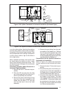
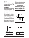
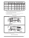
Air From Inside
Air for combustion and ventilation may be taken
from inside the building through an interior wall if
the building is not “tight” and if the total volume
of the furnace space and the space from which
air is drawn meets the volume requirements for
an unconfi ned space. In such cases, the two
openings in the wall must each have free area of
at least one square inch per 1000 Btuh of total
appliance input, but not less than 100 square
inches of free area. See Figure 11. For example,
if the combined input rate of all appliances is less
than or equal to 100,000 Btuh, each opening must
have a free area of at least 100 square inches.
If the combined input rate of all appliances is
120,000 Btuh, each opening must have a free
area of at least 120 square inches.
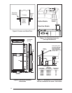
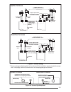
Air Directly Through An Exterior Wall
If combustion air is provided directly through an
exterior wall, the two openings must each have
free area of at least one square inch per 4000
Btuh of total appliance input. (See Figure 12.)
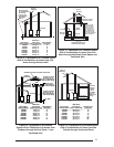
Outdoor Air Through Vertical Openings or
Ducts
If combustion air is provided through vertical ducts
or openings to attics or crawl spaces, the two
openings must each have free area of at least
one square inch per 4000 Btuh of total appliance
input. Ducts must have cross-sectional areas at
least as large as the free area of their respective
openings to the furnace space. Attics or crawl
spaces must communicate freely with the out-
doors if they are the source of air for combustion
and ventilation. (See Figures 13 and 14.)
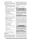
Outdoor Air Through Horizontal
Openings or Ducts
If combustion air is taken from outdoors through
horizontal ducts, the openings must each have
free area of at least one square inch per 2000
Btuh of total appliance input. Ducts must have
cross-sectional area at least as large as the free
area of their respective openings to the furnace
space. (See Figure 15.)
!
CAUTION:
Do not supply combustion air from an
attic space that is equipped with power
ventilation or any other device that may
produce a negative pressure.
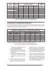
VENTING REQUIREMENTS
This section specifi es installation requirements
for vent and “2-pipe” combustion air piping. For
“one pipe” installations, install vent piping per
this section and provide air for combustion and
ventilation per the previous section. The capacity
table provided in this section applies to the total
of vent and combustion air piping for either type
of installation.
NORDYNE condensing furnaces are classifi ed as
“Category IV” appliances, which require special
venting materials and installation procedures.
Category IV appliances operate with positive
vent pressure and therefore require vent systems
which are thoroughly sealed. They also produce
combustion condensate, which is slightly acidic
and can cause severe corrosion of ordinary vent-
ing materials. Furnace operation can be adversely
affected by restrictive vent and combustion air
piping. Therefore, vent and combustion air piping
lengths must conform completely to the require-
ments of Table 5.
The furnace must be vented to the outdoors. It
must not be vented in common with any other
appliance, even if that appliance is of the condens-
ing type. Common venting can result in severe
corrosion of other appliances or their venting and
can allow combustion gases to escape through
such appliances or vents. Do not vent the furnace
to a fi replace chimney or building chase.
!
WARNING:
FURNACE MUST NOT BE COMMON
VENTED WITH OTHER APPLIANCES.
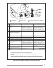
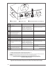
Horizontal Installations
In order to ensure complete drainage of all
condensate, an additional “T” drain assembly
may be installed in line with the vent piping (see
Figures 3 & 4). The “T” assembly may consist
of a 2” PVC tee with a 2’ to 1/2” PVC reducer
bushing , and a barb fi tting. These parts are
available in Horizontal Vent Kit 903568, or they
can be fi eld supplied.