


26
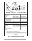
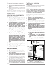
Vent and combustion air piping may be installed
in an existing chimney which is not in use pro-
vided that:
a. Both the exhaust vent and air intake run
the length of the chimney.
b. The top of the chimney is sealed and
weatherproofed.
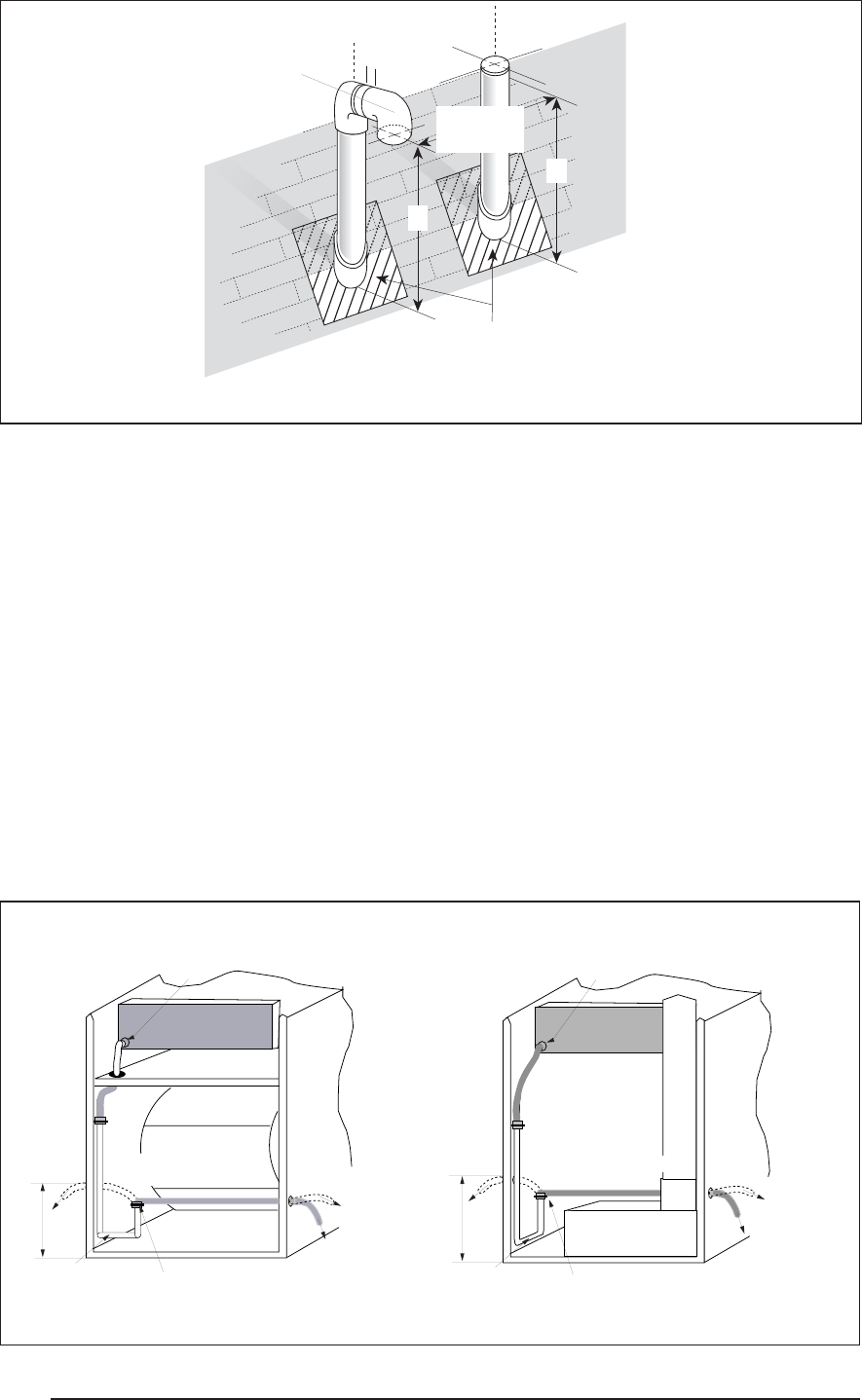
c. The termination clearances shown in
Figure 23 are maintained.
d. No other gas fi red or fuel-burning equip-
ment is vented through the chimney.
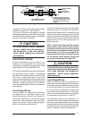
Vent Freezing Protection
When the vent pipe is exposed to temperatures
below freezing, i.e., when it passes through
unheated spaces, chimneys, etc., the pipe
must be insulated with 1/2 inch thick sponge
rubber insulation, Armafl ex-type insulation or
equivalent. Insulating pipe is important to avoid
condensate icing.
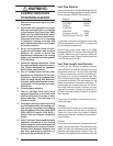
For extremely cold climates or for conditions of
short furnace cycles (i.e. set back thermostat
conditions) the last three feet of vent pipe can be
reduced one nominal pipe size provided that the
total vent length is at least 15 feet in length and
the vent is sized in accordance with the venting
requirements (Table 5) before this reduction is
applied. (Example: 3” to 2-1/2” or 2” to 1-1/2”)
Smaller vent pipes are less susceptible to freez-
ing, but must not be excessively restrictive.
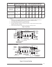
Combustion
Air
Intake
Elbow
Exhaust
Vent
Exhaust
Plumbing Vent Roof Boot
(Typ. Both Pipes)
A
1"
18" Min.
36" Max.
A
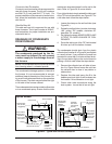
Figure 23. Vertical Vent Termination
A= 12” Above Roof or Snow Accumulation Level
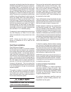
8"
Left Side
Drain
"HARD" J
Drain Tube
Clamp
(Loosen For Step 1)
(Retighten for Step 3)
Route to
floor drain.
...OR
Route to
condensate
pump. Keep
downward
slope.
Collector Box
A
Rotate counter
clockwise (Step 2)
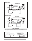
8"
Left
Side
Drain
"HARD" J
Drain Tube
Clamp
(Loosen For Step 1)
(Retighten for Step 3)
Route to
floor drain.
...OR
Route to
condensate
pump. Keep
downward
slope.
Collector Box
A
Rotate clockwise
(Step 2)
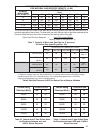
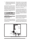
Downfl ow Models
Upfl ow Models
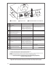
Figure 24. Furnace with Condensate Drain Trap Assembly