


21
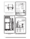
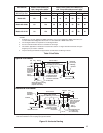
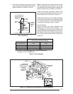
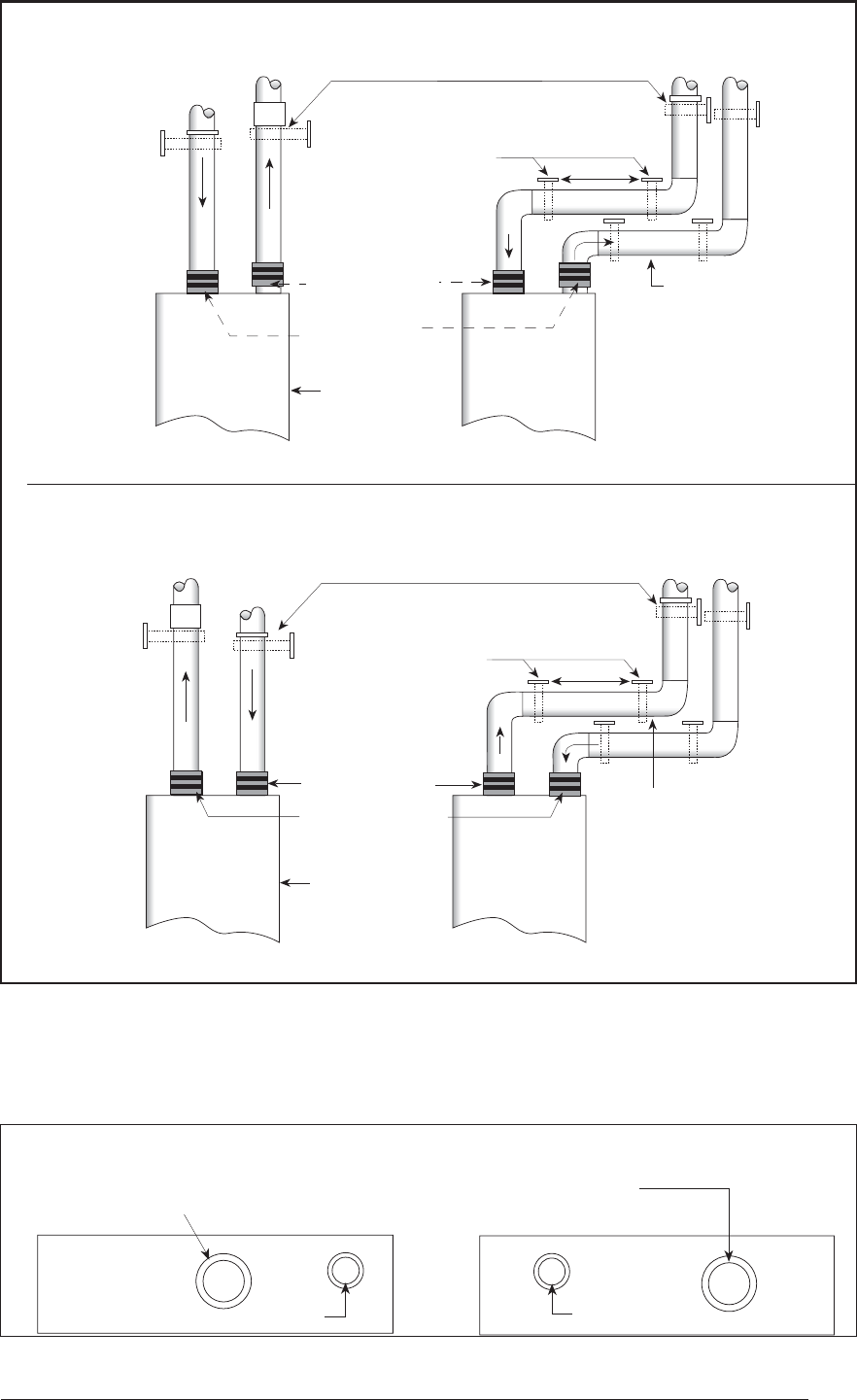
Combustion
Air Pipe
Exhaust
Vent
Cabinet
5'
Support System on
Vertical Rise Below Joints
Support System with
first support as close
to furnace as Possible
Upward Pitch
1/4" per Foot
Furnace Front
Straight Neoprene
Rubber Couplings
with 2 Hose Clamps*
Combustion
Air Pipe
Exhaust
Vent
Cabinet
5'
Support System on
Vertical Rise Below Joints
Support System with
first support as close
to furnace as Possible
Upward Pitch
1/4" per Foot
Furnace Front
Straight Neoprene
Couplings with
2 Hose Clamps*
(Optional - Not
Shown)
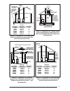
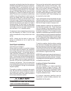
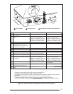
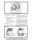
Combustion Air Inlet
2" PVC on 040/060 models,
3" PVC on 080/100 models
2" PVC
Exhaust Vent
All Models
Furnace Top
Downfl ow Furnaces
Upfl ow Furnaces
Downfl ow Furnaces
Upfl ow Furnaces
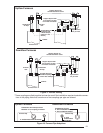
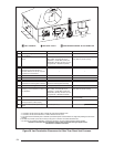
Figure 18. Furnace Pipe Adaptions
Figure 17. Vertical Venting
* These couplings are fi eld-supplied and can be used if the installation requires breakable connec-
tions in the piping. Note that a maximum of two couplings per pipe are allowed.
Combustion Air Inlet Pipe Collar
Diameter 3" for coupling or reducer
Furnace Top
2" PVC Exhaust Vent All Models