


22
!
WARNING:
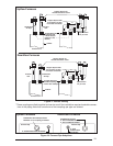
Ensure that the combustion air vent
and the exhaust vent are confi gured as
shown in Figure 19 and 20. Improper
vent termination can cause recir-
culation of the fl ue gases. This may
result in furnace vibration. In severe
cases, the furnace will cycle due to
the intermittent contact between the
fl ame and the fl ame sensor. If you
note oscillations occurring, check the
vent confi guration. Make sure that
the exhaust vent does not have a 90
degree termination.
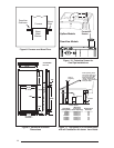
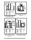
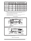
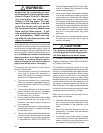
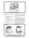
Vent and combustion air intake terminations must
be located to ensure proper furnace operation
and to conform to applicable codes. Figure 19
and 20 illustrates necessary distances from the
vent termination to windows and building air in-
takes. In Canada, the Canadian Fuel Gas Code
takes precedence over these instructions.
Specifi cally, all minimum distance require-
ments with respect to termination of the vent
piping listed below (items 1 through 8).
The following list is a summary of vent terminal
location requirements:
1. The termination must be 12 inches above
snow level or grade level whichever is
higher. See Figure 18 for alternate method
to achieve 12” above snow level.
2. The minimum distance for a (1-pipe instal-
lation) from any door, (openable) window, or
gravity air inlet is 4 ft. below, 4 ft. horizontally,
or 1 ft. above.
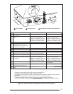
3. The minimum distance for a direct vent (2-
pipe) installation from any door, (openable)
window, or air gravity inlet is 1 ft. below, 1
ft. horizontally, or 1 ft. above.
4. For one-pipe installations the recommended
minimum distance from an inside corner
formed by two exterior walls is 6 feet, but
is not required.
5. The vent termination for a 1-pipe installation
shall be a minimum of 3 ft. above any forced
air inlet within 10 ft.
6. The vent termination shall be located at least
3 ft. horizontally from any electric meter, gas
meter, regulator and any relief equipment
in accordance to ANSI 2223.1/NFPA S4.
These distances apply ONLY to U.S. instal-
lations. In Canada, the Canadian Fuel Gas
Code takes precedence.
7. Avoid areas where condensate drainage
may cause problems by dropping on plant-
ers or patios, etc. Also ensure that exhaust
gases will not impinge on windows or build-
ing surfaces, which may be compromised or
damaged by condensation. Do not install the
vent terminal such that exhaust is directed
into window wells, stairwells, under decks
or into alcoves or similar recessed areas,
and do not terminate above any public
walkways.
8. Select the point of wall penetration where
the minimum 1/4 inch per foot of slope up
can be maintained.
!
CAUTION:
For optimum performance, vent fur-
nace through wall which experiences
the least exposure to winter winds.
For Canadian installations please refer to the
Canadian Installation Code (CAN/CGA-B149.1
or 2) and/or local codes.
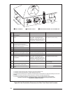
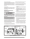
The horizontal venting kits consist of two face
plates and an insulating gasket to seal the exterior
surface. A hole sized closely to the pipe diameter
must fi rst be cut through the wall. A short length
of pipe is then cut such that it can penetrate
the wall and be held in place by closely fi tting
standard couplings. The face plates are retained
on both sides of the wall by the couplings, and
the gasket is retained against the wall by the
outer face plate. Face plates must be fastened
to the wall and the outside one must be fl ashed
as appropriate to prevent entry of water.
When the horizontal kits are not used, the fol-
lowing steps are required:
1. Check the hole size cut through the exterior
wall. Insure that the hole diameter is less
than the diameter of the couplings to be
used.
2. Extend the vent pipe through the wall ap-
proximately 1” and seal the area between
the wall and pipe.
3. If required by local code, apply couplings
to the vent pipe on the interior and exterior
sides of the wall to insure the pipe can not
be pushed or pulled through the wall.