


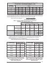
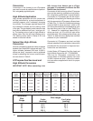

33
6. Adjustments to the fi ring rate can be made
by adjusting the gas manifold pressure.
See the High Altitude Application section
for additional information of fi ring rate at
elevations above 2000 ft.
The manifold pressure must be set to the ap-
propriate value for your installation. Refer to
either Table 8 for natural gas or Table 9 for
LP/propane gas to verify the manifold pressure
setting required for your particular installation. To
adjust the manifold pressure, remove the regula-
tor cap and turn the adjusting screw clockwise
to increase pressure or counterclockwise to
reduce pressure. Replace the regulator cap
after adjustments are complete.
!
CAUTION:
Do not re-drill the burner orifi ces. If
the orifi ce size must be changed, use
only new orifi ces.
Verifying and Adjusting
Temperature Rise
Verify that the temperature rise through the
furnace is within the range specifi ed on the
furnace rating plate. Temperature rises outside
the specifi ed range could result in premature
heat exchanger failure.
Place thermometers in the return and supply
air stream as close to the furnace as possible.
The thermometer on the supply air side must
be shielded from direct radiation from the heat
exchanger to avoid false readings. Adjust all
registers and duct dampers to the desired
position and run the furnace for fi fteen minutes
before taking any temperature readings. The
temperature rise is the difference between the
supply and return air temperatures.
For typical duct systems, the temperature rise
will fall within the range specifi ed on the rat-
ing plate with the blower speed at the factory
recommended setting. If the temperature rise
measured is outside the range specifi ed, it may
be necessary to change the blower speed. Lower
blower speeds will increase the temperature
rise and higher blower speeds will decrease the
temperature rise.
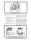
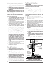
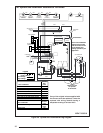
The furnace is equipped with a multispeed motor.
Heating and cooling speed selection is made by
moving the leads on the integrated control board
located in the furnace. The wiring diagram on
the furnace and Figures 27, 28 and 29 show the
speed taps for adjusting motor speed.
If it is desired that the blower operate at the
same speed for heating and cooling, tape off
the terminal of the unused blower wire. Install
the jumper wire, found in the plastic instruction
bag, across the HEAT and COOL taps on the
Figure 28. Blower Speed Tap Location
R C Y G W
Flame Signal
Light (Yellow)
3 Amp Fuse
COM
24 V
HUM
Neutrals
41
52
63
7
8
9
4
5
6
1
2
3
EAC
HUM
M1
M2
M3
HEAT
COOL
L1
XFMR
Unused Motor
Leads
EAC
Electronic Air Tap
(.5A@ 120 VAC)
Status
Light (Red)
Humidifier Tap
(.5A@ 120 VAC)
Connect
Neutral
Lead of
Electronic
Air Cleaner
and/or Humidifier
Here.
Common
Leads
Coolin
g
S
p
eed Ta
p
Heating
Speed Tap