


37
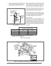
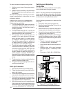
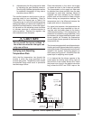
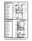
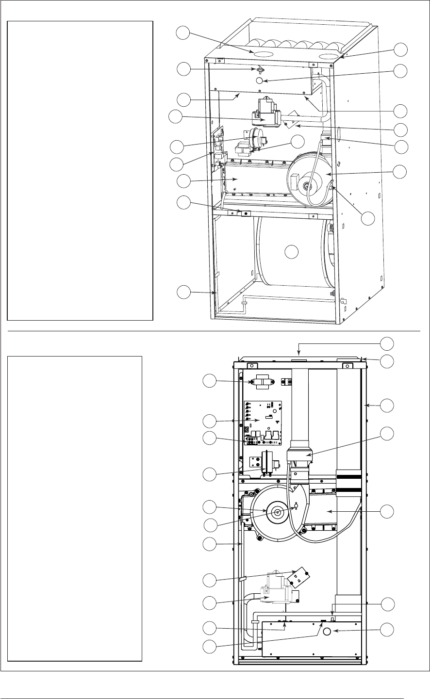
Figure 30. Location of Major Components
1 Igniter (Not Shown)
2 Flame Sensor (Not
Shown)
3 Gas Valve
4 Flame Roll-out
Switch(s)
5 Pressure Switch
7 Control Board
8 Blower Door
Switch
9 Vent Safety Switch
10 Low Voltage
Transformer
11 Supply Air Limit
Switch
12 Circulating Air
Blower Assembly-
13 Induced Draft
Blower
14 Condensate Drain
Tube
15 In-Line Drain
Assembly
16 Burner View Port
17 Front Header Box
18 Combustion Air
Intake
19 Exhaust Vent
Upfl ow Furnace Models
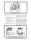
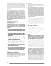
1 Igniter (Not Shown)
2 Flame Sensor (Not
Shown)
3 Gas Valve
4 Flame Roll-out Switch(s)
5 Pressure Switch
6 Vent Pressure Switch
(Not Shown)
7 Control Board
8 Blower Door
Switch
9 Vent Safety Switch
10 Low Voltage
Transformer
11 Supply Air Limit
Switch
12 Circulating Air
Blower Assembly-
13 Induced Draft
Blower
14 Condensate Drain Tube
15 In-Line Drain
Assembly
16 Burner View Port
17 Front Header Box
18 Combustion Air
Intake
19 Exhaust Vent
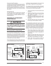
1
2
3
4
9
10
11
12
17
19
5
7
8
13
14
15
16
18
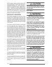
Downfl ow Furnace Models
1
2
3
4
9
10
11
12
17
19
5
7
8
13
14
15
16
18