


11
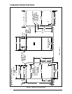
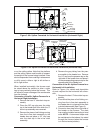
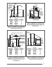
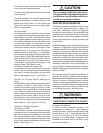
Figure 3. 90+ Upfl ow Converted for Horizontal Installation (Horizontal Right)
5/8" Vinyl Cap
1/4" Vinyl Cap
Drain Trap
1/2" Vinyl
Cap
Soft
Tubing
PVC Tee
Soft Tubing
Looped to Provide
a Drain Trap
3" to 2"
Reducer
(Optional)
PVC Reducer
Bushing
Pressure Switch
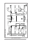
Grey
Tubing
Soft Tubing
1/4" Vinyl Cap
Grey
Tubing
Drain Trap
Soft
Tubing
PVC Tee
Soft Tubing
Looped to Provide
a Drain Trap
3" to 2"
Reducer
(Optional)
Drainage Port
is Downard
Reducer
Bushing
Alternative
for
Horizontal
Vent
Pressure
Switch
Pressure Switch
(Condensate)
Vinyl Cap
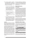
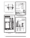
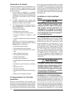
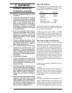
Figure 4. 90+ Upfl ow Converted for Horizontal Installation (Horizontal Left)
or on the ceiling rafters. Note that the platform
and the ceiling rafters must be able to support
the weight of the furnace being installed. It can
also be suspended from a ceiling in a basement
or utility room in either a right to left airfl ow or
left to right airfl ow.
When installed horizontally, the furnace must
be raised above the surface to allow a drain
trap to hang vertically below the furnace. This
will allow for proper drainage of the condensate
from the furnace.
Conversion of the 90+ Upfl ow Furnace for a
Horizontal Right Installation.
1. Remove the hard “J” tube drain trap as-
sembly.
2. Place the 5/8” cap plug over the drain
tap in the header box from which the “J”
drain trap assembly was removed.
3. Remove the piece of soft tubing running
from the in-line drain assembly to the
header box and place a 1/2” vinyl cap
over the drain tap in the in-line drain
assembly.
4. Remove the grey tubing from the pres-
sure switch to the header box. Remove
the 1/4” cap from the pressure tap on the
right side of the header box and place it
on the corresponding pressure tap on the
opposite side of the header box.
Conversion of the 90+ Upfl ow Furnace for a
Horizontal Left Installation.
Refer to Figure 4 for details and description
of parts required for the horizontal left conver-
sion.
1. Remove the hard “J” tube drain trap as-
sembly.
2. Ensure that the piece of soft tubing run-
ning from the in-line drain assembly to
the header box is in place with the drain
oriented downwards (See Figure 4).
3. Connect a draw trap to the right side of
the header on the furnace. The drain
trap must be installed according to local
code. NOTE: A downward slope must
be maintained on the tube as it is routed
through the furnace (when the furnace
is in the horizontal position).