


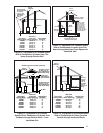

20
equivalent vent length is less than the maximum
allowable vent length. Returning to our example,
we consult Table 5 and determine that for an
80,000 Btu/h furnace the maximum vent length
for 2” diameter piping is 60 feet or for 3” diameter
piping is 150 feet. Note that the maximum vent
length given in Table 5 includes one long radius
elbow. Therefore, for our example, we have three
additional long radius elbows for which we must
add to our piping. Each long radius elbow is
equivalent to 2.5 feet, so we must add 7.5 feet
to our vent length. Therefore, the equivalent vent
length for our installation is 47.5 feet. We compare
this with the maximum vent length for 2” and 3”
diameter piping. For both cases, our equivalent
vent length is less than the maximum allowable
vent length, so for our “one-pipe” installation we
can use either 2” or 3” diameter piping.
Condensing furnace combustion products have
very little buoyancy, so Table 5 is to be used
without consideration of any vertical rise in the
piping.
NOTE: Always use the same or larger size
piping for combustion air as is used for the
exhaust vent.
Vent Pipe Installation
Pipe Routing and Support
Route piping as directly as possible between
the furnace and the outdoors and remember
that routing affects pipe size requirements per
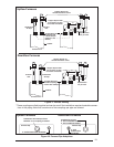
the preceding section. If a two pipe system is
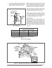
used, locate the combustion air intake and the
vent exhaust in the same atmospheric pressure
zone - i.e. both must exit the building though the
same portion of exterior wall or roof (See Figure
22). Vent piping must be sloped upwards not
less than 1/4” per foot in the direction from the
furnace to the terminal. This is to ensure that
any condensate fl ows back to the furnace (where
it can be disposed of through the condensate
disposal system).
The quality of outdoor air must also be consid-
ered. Be sure that the combustion air intake is
not located near a source of solvent fumes or
other chemicals which can cause corrosion of
the furnace combustion system.
!
CAUTION:
Combustion air must not be drawn
from a corrosive atmosphere.
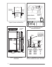
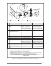
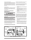
Piping must be mechanically supported so that
its weight does not bear on the furnace. Sup-
ports must be at intervals no greater than fi ve
feet, and at smaller intervals if necessary to
ensure that there are no sagging sections to
trap water. (See Figure 16.) It is recommended
to install couplings along the vent pipe, on either
side of the exterior wall. These couplings may
be required by local code.
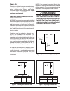
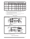
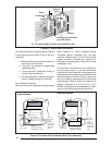
Figure 18 illustrates vent and combustion air pipe
sizes exiting the furnace. Transition to the correct
pipe size must be done close to the furnace so
that the full length of pipe is of proper size.
Straight neoprene couplings are supplied with
the downfl ow furnaces only. These couplings
are to be installed in the combustion air inlet (if
present) and exhaust vent piping at the furnace
as shown in Figures 16. For an upfl ow furnace
installation, if breakable connections are required
in the combustion air inlet (if present) and exhaust
vent piping, then straight neoprene couplings for
2” or 3” piping with hose clamps can be used.
These couplings can be ordered through your
local furnace distributor.
To install a coupling, slide the rubber coupling
over the end of the pipe that is attached to the
furnace and secure it with one of the hose clamps.
Then slide the other end of the rubber coupling
onto the other pipe from the vent and secure the
coupling with the second hose clamp. Ensure that
the connection is tight and leak free.
NORDYNE condensing furnaces have been certi-
fi ed for installation with zero clearance between
vent piping and combustible surfaces. However,
it is good practice to allow space for convenience
in installation and service.
Location of Outdoor Terminations
Horizontal Venting
Vent and combustion air intake terminations
must be as shown in Figure 19 and 20. Vent
termination clearances shall be consistent with
the National Fuel Gas Code, ANSI 2223.1/NFPA
54 and/or the CSA B149.1, Natural Gas and
Propane Installation Code.
All minimum clearances specifi ed must be
maintained to protect building materials from
degradation by fl ue gases.