


9
ENGLISH
8. Installation of unit
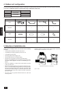
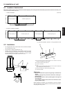
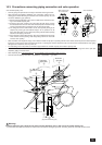
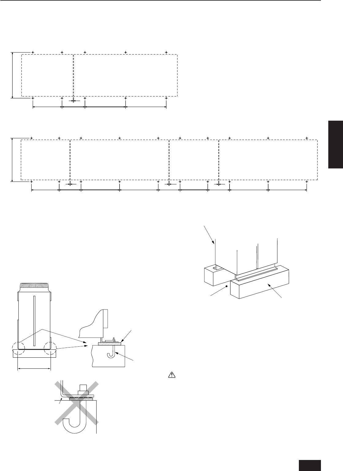
8.1. Location of anchor bolt
Mount the constant capacity unit on the left and variable capacity unit on the right of the same frame (as seen from the front of the unit). Allow
10 mm of clearance between the units.
• Individual installation (Unit: mm)
Service side
880±5
10
780±2780±2440560±2
Constant capacity unit
Variable capacity unit
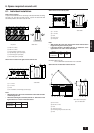
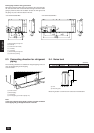
• Example of collective installation
1010
440 780±2780±2440560±2
Service side
880±5
Constant capacity unit
Variable capacity unit
10
780±2780±2440560±2
Constant capacity unit
Variable capacity unit
For collective installation, provide a 10 mm gap between units.
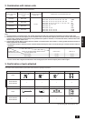
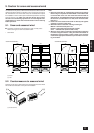
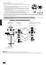
8.2. Installation
• Fix unit tightly with bolts as shown below so that unit will not fall down
due to earthquake or gust.
• Use concrete or angle for foundation of unit.
• Vibration may be transmitted to the installation section and noise
and vibration may be generated from the floor and walls, depending
on the installation conditions. Therefore, provide ample
vibrationproofing (cushion pads, cushion frame, etc.).
880±5
A
B
C
D
E
F
A Be sure that the corners are firmly seated. If the corners are not firmly
seated, the installation feet may be bent.
B M10 anchor bolt procured at the site.
C Corner is not seated.
D Unit
(provide ample vibrationproofing between the unit and the foundation by
using cushion pads, cushion frame, etc.)
E Piping and wiring space (bottom piping, bottom wiring)
F Concrete foundation
Warning:
• Be sure to install unit in a place strong enough to withstand its
weight.
Any lack of strength may cause unit to fall down, resulting in a
personal injury.
• Have installation work in order to protect against a strong wind
and earthquake.
Any installation deficiency may cause unit to fall down, result-
ing in a personal injury.
When building the foundation, give full attention to the floor strength,
drain water disposal <during operation, drain water flows out of the unit>,
and piping and wiring routes.