


32
ENGLISH
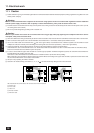
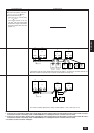
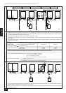
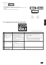
C. Example of a system using the transmission booster (Combination of systems A - C)
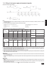
Example of transmission line wiring
a. Address settings are the same as for wiring connection examples A and B.
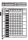
b. Let the number of indoor units and remote control units connected be within the limit for the number of units shown in the following table for
the total of the number of units connected between the variable capacity unit (OC) and the transmission booster (RP) N1 and the number of
units connected after the transmission booster (RP) N2.
c. Connect the power supply ground to the transmission booster (RP) securely.
Connect the transmission lines of the outdoor unit side to terminals A and B of transmission line terminal block 1 (TB2) of the transmission
booster (RP).
Connect the transmission lines of the expansion indoor unit side to terminals A and B of the of transmission line terminal block 2 (TB3) of the
transmission booster (RP).
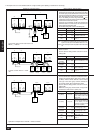
The number of indoor units and the total number of remote controllers is displayed within the parenthesis ( ).
*1 If even one unit that is higher than 200 exists in the cooling system, the maximum capacity will be “200 or higher”.
200 or lower
200 or higher
Remote controller PAR-F 25MA
Prior to Ver. E After Ver. F
16 (32) 20 (40)
16 (32) 16 (32)
(*1)
Capability of the
connected indoor units
Remote controller type
Number of connected indoor units that can be
connected without a RP.
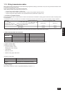
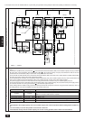
Permissible length
• Indoor system maximum remote wiring length: 1 L1+L2+L3+L5+L6
=
200 m (1.25 mm
2
)
2 L1+L2+L3+L5+L7
=
200 m (1.25 mm
2
)
3 L1+L2+L4
=
200 m (1.25 mm
2
)
4 L6+L5+L3+L4, L4+L3+L5+L7
=
200 m (1.25 mm
2
)
• Remote control wiring length : r1, r2
=
10 m (0.5 to 0.75 mm
2
)
If the length exceeds 10 m, use 1.25 mm
2
shielded cable and calculate the length of that portion (L4 and L7)
as within the total extended length and the longest remote length.
Prohibited items
• Do not mistake the connection locations of transmission booster (RP) transmission line terminal block 1 (TB2) and transmission line termi-
nal block 2 (TB3). (Operation will not be normal in such a case.)
• Do not connect the S terminals of transmission line terminal block 1 (TB2) and transmission line terminal block 2 (TB3) of the transmission
booster (RP) together.
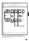
M1 M2
M1 M2 S
TB3
TB3
RC
N
1
N
2
IC
M1M2 S
TB5
IC
M1M2 S
TB5
123
TB13
123
TB13
RP
Ground
ABS
TB2
ABS
TB3
L1
L4r1
L2 L3 L5 L6
TB6
OCOS
L7r1
RC
TB6
IC
M1M2 S
TB5
IC
M1M2 S
TB5
123
TB13
123
TB13
M1 M2
M1 M2 S
TB3
TB3
RC
IC
M1M2 S
TB5
IC
M1M2 S
TB5
123
TB13
123
TB13
RP
Ground
AB S
TB2
AB S
TB3
TB6
OCOS
RC
TB6
IC
M1M2 S
TB5
IC
M1M2 S
TB5
123
TB13
123
TB13
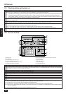
Wiring method, address setting method