


28
ENGLISH
M1M2
M1M2 S
OC
IC
(51)
M1M2 S
TB5
RC
RC
(01)
L
1
L
3
r
1
r
2
L
2
TB6
(101)
TB6
(102)
TB3 TB7
123
TB13
IC
M1M2 S
TB5
(02)
123
TB13
M1 M2 S
OS
(52)
TB3
Shielded cable
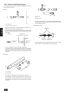
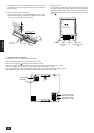
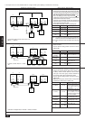
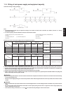
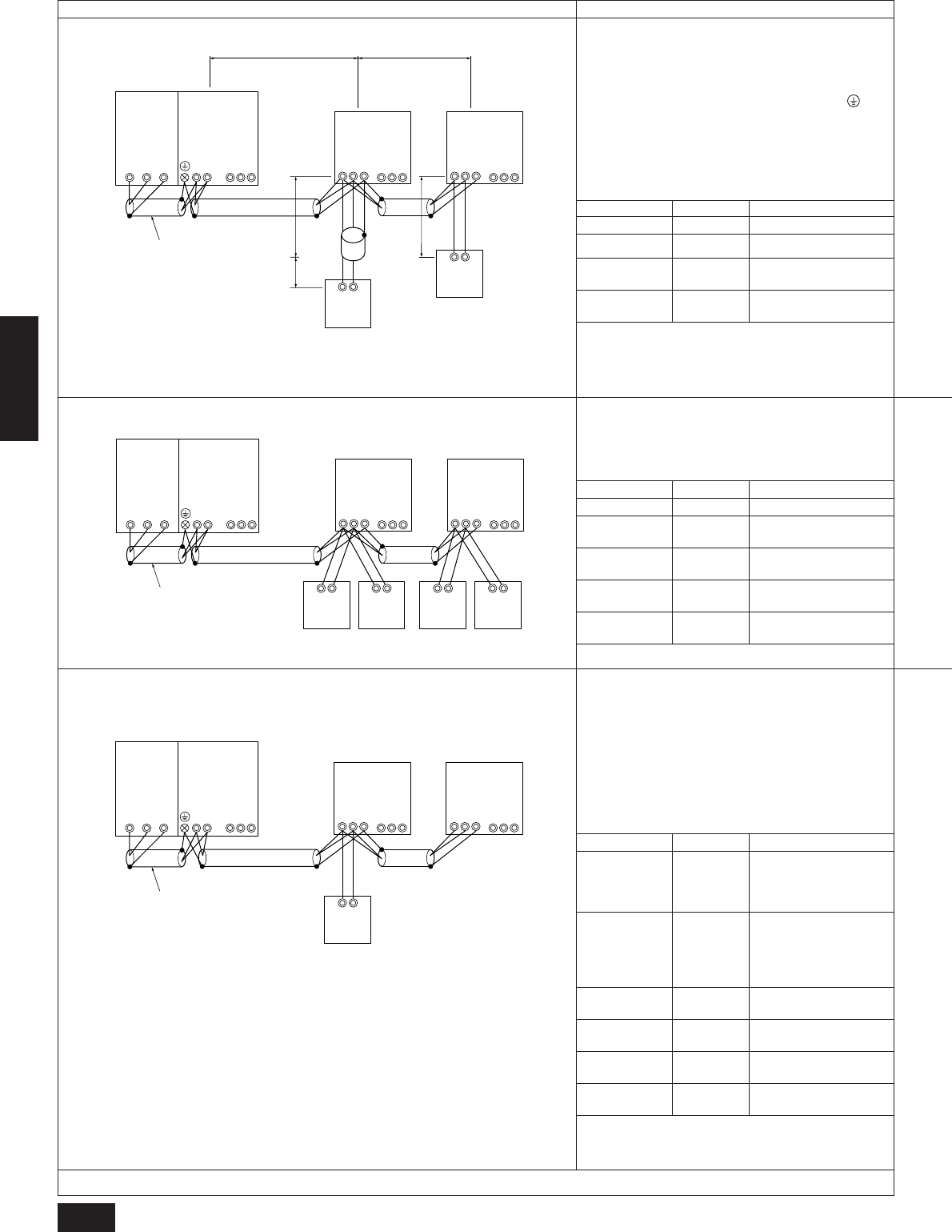
A. Example of the use of the shielded cable in a single coolant system (Setting of addresses is necessary)
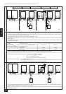
Example of control line wiring Wiring method, address setting
1) Standard
• One remote control unit for each indoor unit
Within ( ): Address
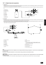
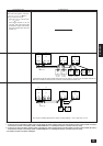
2) 2 Remote control operation
3) Group operation
• 2 remote control units for 1 indoor
unit.
• Operation of multiple indoor units with 1 remote controller.
a. Same as above.
b. Same as above.
c. Set the address setting switch as shown in the fol-
lowing table.
a. Same as above.
b. Connect terminals A and B (M1 and M2) of the trans-
mission line terminal block (TB5) of the indoor unit
(IC Main) with the lowest address of all the indoor
units (IC) in the same group and the terminals on
the remote control (RC) terminal block (TB6).
c. Set the address setting switch as shown in the fol-
lowing table.
d. Within the same group, let the indoor unit (IC) which
functions the most be the IC (Main) unit.
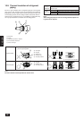
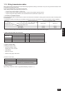
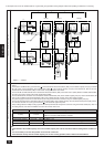
a.
Run the wire to terminals M1 and M2 the variable capacity unit (OC)
transmission line terminal block (TB3) and to terminals M1 and M2 on
the constant capacity unit (OS) transmission line terminal block (TB3)
as well as to the terminals M1 and M2 of the transmission line terminal
block (TB5) of each indoor unit (IC). (Two-wire, no polarity)
Also, run the shielded ground wire to the ground terminal of the
variable capacity unit, the S terminal of the constant capacity unit (TB3),
and the S terminal of each indoor unit (TB5).
b.
Connect the wires to terminals M1 and M2 of the transmission line
terminal block (TB5) in each indoor unit (IC) and connect them to the
remote control (RC) terminal block (TB6).
c.
Set the address setting switch as shown in the following table.
RC
TB6
(101)
M1M2
M1M2 S
OC
(51)
TB3 TB7
M1 M2 S
OS
(52)
TB3
IC (Main)
M1M2 S
TB5
(01)
123
TB13
IC (Sub)
M1M2 S
TB5
(02)
123
TB13
Shielded cable
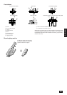
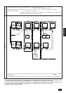
1) ~ 3) above can be combined.
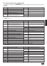
Unit
Indoor unit
Remote control
Variable capacity
unit
Constant capacity
unit
Range
01 to 50
101 to 150
Note 2
51 to 100
Note 1
51 to 100
Note 1
Setting method
—
Indoor unit address + 100
The smallest address of
the indoor units + 50
Variable capacity unit ad-
dress + 1
Setting method
—
Indoor unit address + 100
Indoor unit address + 150
The smallest address of the
indoor units + 50
Variable capacity unit ad-
dress + 1
Range
01 to 50
101 to 150
Note 2
151 to 200
Note 2
51 to 100
Note 1
51 to 100
Note 1
Unit
Indoor unit
Main remote
controller
Sub remote
controller
Variable capacity
unit
Constant capacity
unit
Range
01 to 50
01 to 50
101 to 150
Note 2
151 to 200
Note 2
51 to 100
Note 1
51 to 100
Note 1
Unit
IC (Main)
IC (Sub)
Main remote
controller
Sub remote
controller
Variable capacity
unit
Constant capacity
unit
Setting method
Address of the indoor unit
with the smallest address of
all the indoor units in the
same group.
Address of any of the indoor
units except the address of
the IC (Main). Let the
number be in sequence with
that of the IC (Main)
Address of the IC (Main) in
the same group + 100
Address of the IC (Main) in
the same group + 150
The smallest address of the
indoor units + 50
Variable capacity unit ad-
dress + 1
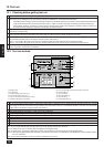
(Main remote
controller)
(Sub remote
controller)
(Main remote
controller)
(Sub remote
controller)
RC
TB6
(101)
RC
TB6
(151)
RC
TB6
(102)
RC
TB6
(152)
M1M2
M1M2 S
OCOS
(51)
TB3 TB7
M1 M2 S
(52)
TB3
IC
M1M2 S
TB5
(01)
123
TB13
IC
M1M2 S
TB5
(02)
123
TB13
Shielded cable
Note 1
If the address of the variable capacity unit or the constant capac-
ity unit is set at 100, set one of the address switches at 01 ~ 50.
Note 2
It is not necessary to set the 100’s position in the remote control
unit.
Notes 1, 2. Same as above.
Notes 1, 2. Same as above.