


14
ENGLISH
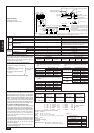
Piping components Tolerance
A+B+C+D+E+F+a+b+c+d+e+f 220 m or less
A (B)+C+D+E+c 100 m or less (Max. equivalent length 125 m)
D+E+c 40 m or less
I
A, B (Liquid line) 4 m or less (Max. equivalent length 5 m)
A (Gas line) 4 m or less (Max. equivalent length 5 m)
H 50 m or less
H 40 m or less
h 15 m or less
–
Must be installed on same frame, and there must be no high/low difference.
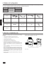
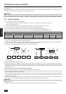
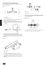
Select the branch kit, sold separately, from the table below. (Each kit contains a refrigerant and gas piping set.)
Line branching Header branching
CMY-Y102S-C CMY-Y102L-C CMY-Y202-C CMY-Y302-C
CMY-Y104 CMY-Y107 CMY-Y1010
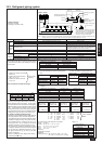
(1) Refrigerant piping diameter in section from out-
door unit to first branch (outdoor unit piping diam-
eter)
Model
Piping diameter (mm)
Liquid line Gas line
PUHY-600YSMC ø19.05 ø38.1
PUHY-650YSMC ø19.05 ø44.45
PUHY-700YSMC ø19.05 ø44.45
PUHY-750YSMC ø19.05 ø44.45
(2) Refrigerant piping diameter in section from
branch to indoor unit (indoor unit piping diam-
eter)
Model number Piping diameter (mm)
22 · 28 · 36 · 45
Liquid line ø6.35
Gas line ø12.7
56 to 90
Liquid line ø9.52
Gas line ø15.88
112 · 140 · 160
Liquid line ø9.52
Gas line ø19.05
224
Liquid line ø12.7
Gas line ø25.4
280
Liquid line ø12.7
Gas line ø28.6
Total of units downstream
less than 180
Total of units downstream
181 to 370
4 branching
header
(3) Refrigerant piping diameter in section from branch
to branch
Downstream unit model total
Liquid line (mm) Gas line (mm)
90 or less ø9.52 ø15.88
91 to 180 ø12.7 ø19.05
181 to 370 ø12.7 ø25.4
371 to 540 ø15.88 ø31.75
541 to 710 ø15.88 ø38.1
711 or more ø19.05 ø44.45
7 branching
header
10 branching
header
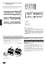
+++++ α
<Example> Indoor 1 : 125 A : ø12.7 3 m a :ø9.52 10 m
2 : 125 B : ø15.88 1 m b :ø9.52 5 m
3 : 125 C : ø19.05 30 m c :ø9.52 5 m
4 : 125 D : ø15.88 10 m d :ø9.52 10 m
5 : 100 E : ø12.7 5 m e :ø9.52 15 m
6:40 F:ø12.7 15 m f :ø6.35 5 m
The total length of each liquid line is as follows
ø19.05 : C = 30 m
ø15.88 : B + D = 1 + 10 = 11 m
ø12.7 : A + E + F = 3 + 5 + 15 = 23 m
ø9.52 : a + b + c + d + e = 10 + 5 + 5 + 10 + 15 = 45 m
ø6.35 : f = 5 m
Therefore,
<Calculation example>
Additional
refrigerant charge = 30 × 0.29 +11 × 0.25 + 23 × 0.12 +
45 × 0.06 + 5 × 0.024 + 3.0 = 20.1 kg
Value of α
Total capacity of
connecting indoor units
α
to Model 80 1.0 kg
Models 81 to 160 1.5 kg
Models 161 to 330 2.0 kg
Models 331 to 480 2.5 kg
Models 481 or more 3.0 kg
At the conditions
below:
<Additional charge>
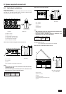
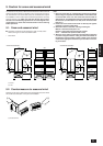
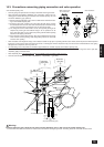
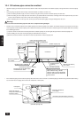
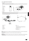
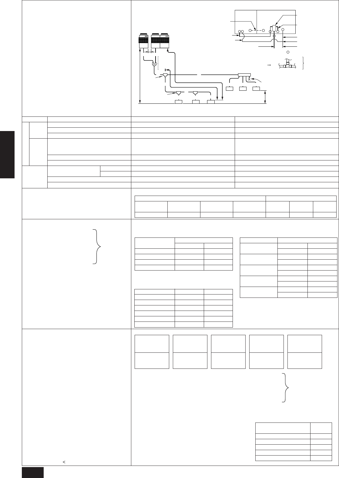
Multiple line/header
Connection examples
(connecting to six indoor units)
Item
Total piping length
Farthest piping length (L)
Farthest piping length after first branch (r)
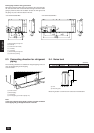
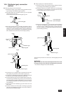
Oil balance pipe
Distributer (liquid)/Variable capacity unit, Constant capacity unit
Distributer (gas)/Constant capacity unit
Indoor/Outdoor
Outdoor upper
Outdoor lower
Indoor/Indoor
Variable capacity unit/Constant capacity unit
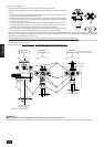
■ Selecting the refrigerant branch kit
Use the table to the right to make the selection based
on the model total of indoor units downstream from the
branch section or on the number of indoor units to be
connected on the header branch.
■ Select each section of refrigerant piping
(1) Section from outdoor unit to first
branch (C)
(2) Sections from branch to indoor
unit (a, b, c, d, e, f)
(3) Section from branch to branch
(D, E, F)
Select the size from the table to the right.
■
Additional refrigerant charge
The outdoor unit is charged with refrigerant at the time of
shipping according to the chart above. As this charge
does not include the amount needed for extended piping,
additional charging for each refrigerant line will be required
on site. In order that future servicing may be properly
provided, always keep a record of the size and length of
each refrigerant line and the amount of additional charge
by writing it in the space provided on the outdoor unit.
■
Calculation of additional refrigerant charge
•
Calculate the amount of additional charge based on the length
of the piping extension and the size of the refrigerant line.
•
Use the table to the right as guide to calculating the amount
of additional charging and charge the system according.
• If the calculation results in a fraction of less than 0.1
kg, round up to the next 0.1 kg. For example, if the
result of the calculation was 20.03 kg, round the re-
sult up to 20.1 kg.
• If the total amount of refrigerant including the amount
of refrigerant sealed in the outdoor unit when shipped
from the factor plus additional refrigerant for exten-
sion piping exceeds 73 kg, use 73 kg as the total
amount of refrigerant.
Amount of refrigerant when shipped from factory +
added refrigerant
=
73 kg
Total of units downstream
more than 711
Permissible high/
Low difference
The included oil balance pipe must be used. If any other piping is used, the length
of the oil balance pipe must be no more than 3 m (max. equivalent length 4 m),
and height from the bottom of the unit must be no more than 0.1 m.
Permissible length
Indoor
side
Outdoor
side
Total of units downstream
371 to 710
Liquid pipe size
total length of
ø19.05 × 0.29
(m) × 0.29 (kg/m)
Liquid pipe size
total length of
ø12.7 × 0.12
(m) × 0.12 (kg/m)
Liquid pipe size
total length of
ø9.52 × 0.06
(m) × 0.06 (kg/m)
Liquid pipe size
total length of
ø6.35 × 0.024
(m) × 0.024 (kg/m)
Liquid pipe size
total length of
ø15.88 × 0.25
(m) × 0.25 (kg/m)
Note:
• The model total for downstream units
shown in the table below is the model
total when viewed from Point A in the
drawing above.
• With the exception of PUHY-600YMC,
the first branch is always CMY-Y302-F.
L
R
H
D
a
c
d
e
h
f
First branch
(branch joint)
In door
unit
In door
unit
In door
unit
In door
unit
In door
unit
In door
unit
6
12
b
3
4
5
Branch joint
Cap
Branch header
Constant
capacity unit
Variable
capacity unit
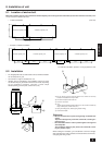
BA
C F
E
G
Distributer
(liquid)
Distributer
(gas)
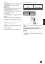
Note 1
Note 1: Because it is built into the variable capacity unit, B is used to carry liquid only. Set the constant capacity unit and
variable capacity unit in accordance with the G dimension given in the figure above (G = 0.01 m).
A
To down stream units
Liquid line (main) CGas line (main) C
Liquid line B
Gas line B
Gas line A
Distributer (gas) (optional)
Distributer (liguid) (optional)
Liquid line A
Oil balance pipe (optional) I
(for distribution within the unit)
Constant
capacity unit
Variable
capacity unit
:indicates piping connection points
Each section
of piping