


18
ENGLISH
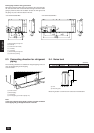
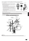
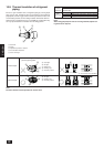
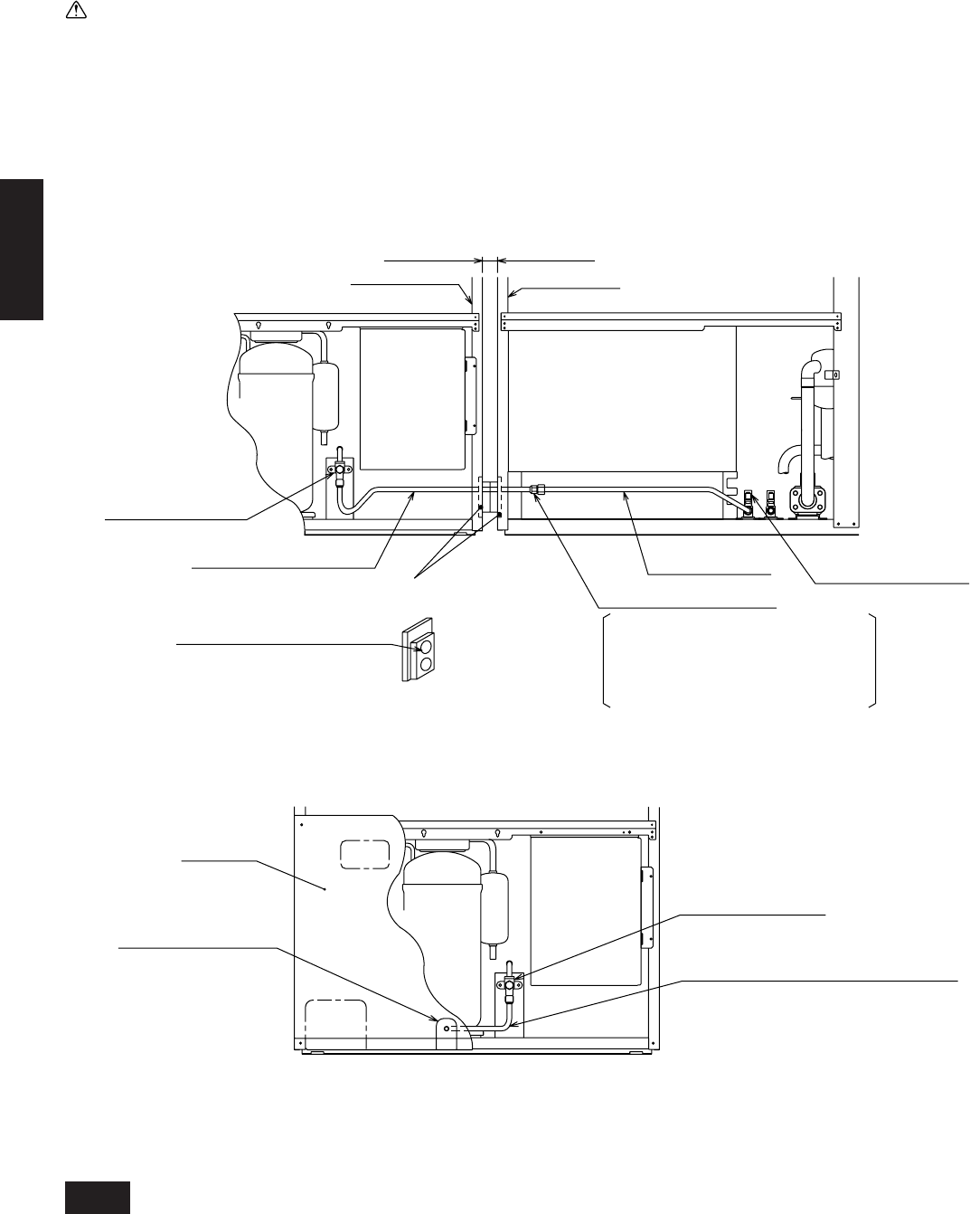
10.4. Oil balance pipe connection method
• Oil balance piping can be took out from the front, bottom or side of the unit (left side for the variable capacity unit, right side for the constant capacity
unit).
• Connect piping and operate valves exactly as described below. (for details, see item 10.3.)
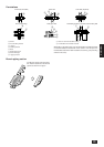
1 After connecting oil balance pipe, be sure to evacuate using the service port of the variable capacity unit side valve.
2 After evacuating, be sure to fully open each valve stem. If you operate with the valve closed, a shortage of oil in the compressor may occur due
to lack of oil flow between units, which could result in damage to the compressor.
3 After completing work, shut the cap of the service port and handle section tightly so that gas leaking does not occur.
Warning:
Failure to connect the oil balance pipe will result in the compressor being damaged.
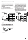
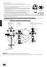
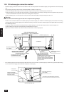
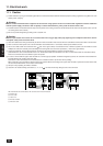
• Provide 10 mm of clearance between the variable capacity and constant capacity units. Position the variable capacity unit so that its front is facing
on the right side and the constant capacity unit so that its front is facing on the left. Connect the oil balance pipe for the optional CMC-30A according
to the following procedure.
1 Open the knock-out holes of the left side panel for the variable capacity unit, and the right side panel for the constant capacity unit.
2 After installing the units, flare-connect the piping included with the unit (ø12.7).
3 Block the clearance between units with the 2 seals included with the constant capacity unit.
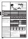
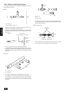
Tightening torque is 55 N·m (550 kg·cm)
Open and close using a double
spanner. Apply a coat of refrigerating
machine oil on both sides of the flare
contact surface.
Ball valve (oil balance)
ø12.7 (flare)
Ball valve (oil balance)
ø12.7 (flare)
(Variable capacity unit)
(Constant capacity unit)
Control boxControl box
Compressor
Flare connection (3 places)
Left side panel
Right side panel
Oil balance pipe 1 (optional)
Oil balance pipe 2
(optional)
Seal material (2 pieces, included)
Through holes for oil balance pipe
and transmission cables
10 mm (clearance between units)
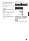
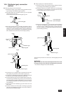
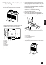
• If the oil balance piping for the constant capacity unit from the front of the unit is took out, bend the piping as shown in the figure below. (When doing
so, be careful not to the piping doesn’t touch the compressor or other parts.)
Ball valve (oil balance)
ø12.7 (flare)
Oil balance pipe (Bend piping at the site.)
Knock-out holes for
taking out oil balance pipe
from front surface
(Constant capacity unit)
Front panel
Compressor
Control box