


26
ENGLISH
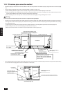
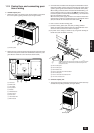
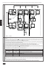
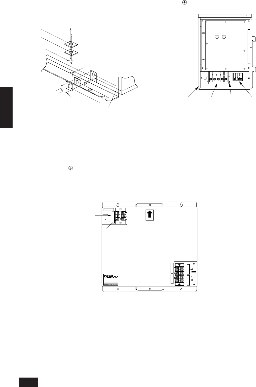
2. The control box cover is removed by removing the 2 screws and pull-
ing downward. (The control box with the cover removed is shown in
the figure below.)
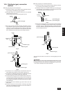
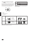
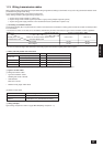
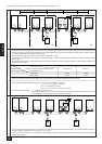
3. Method of using conduit mounting plate
The equipment includes conduit mounting plates (ø27, ø33, ø40).
Select the mounting plate according to the diameter of the conduit
used, and mount as shown in the figure below.
If conduit is connected
from the bottom
ø40
mounting plate
ø27 mounting plate
ø27 mounting plate
ø33 mounting plate
ø40
Knock-out hole
Tapping screw
Unit front
If conduit is connected
from the front
ø33 mounting plate
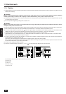
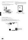
4. Piping connection
Connect indoor unit crossover cables of the transmission cables ter-
minal block (TB3) of the variable capacity unit to the transmission
cables terminal block (TB3). When making an indoor/outdoor con-
nection with shielded wiring, connect the shield ground to the earth
screw ( ).
CONT. board
Power
terminal block
(TB1)
Earth screw
(E)
Transmission
cables terminal block
(TB3)
Controlbox
10 1
Address
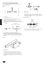
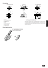
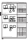
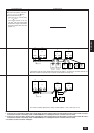
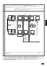
c. Transmission booster (optional)
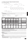
(For details, see item 11.3. “Wiring transmission cables”)
Connect 220/230/240 VAC to L/N of power terminal block (TB1).
Connect the ground to the terminal of power terminal block (TB1).
Connect the outdoor unit side transmission cables to A/B of transmission cables terminal block 1 (TB2).
Connect the outdoor unit side shield to S of transmission cables terminal block 1 (TB2).
Connect additional indoor unit side transmission cables to A/B of transmission cables terminal block 2 (TB3).
Connect additional indoor unit side shield to S of transmission cables terminal block 2 (TB3).
LN
TB1
TB 2 TB 3
220V-240V ~/N
UP
AB
BA
SS
Transmission cables
terminal block 2 (TB3)
Earth
Transmission cables
terminal block 1 (TB2)
Power terminal
block (TB1)