


31
ENGLISH
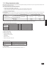
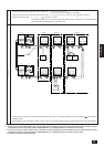
Group 1 Group 3 Group 5
M1 M2
M1M2 S
TB7
M1 M2 S
TB3
TB3
(51)
RC
IC
(02)
IC
M1M2 S
TB5
M1M2 S
TB5
(01)
IC
M1M2 S
TB5
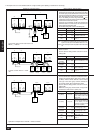
123
TB13
123
TB13
123
TB13
IC
(03)
M1M2 S
TB5
123
TB13
IC
(07)
M1M2 S
TB5
123
TB13
(04)
TB6
(101)
RC
TB6
(105)
RC
TB6
(103)
RC
TB6
(155)
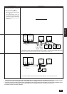
CN40
OC
(54)
OS
M1 M2
M1M2 S
TB7
TB3
(52)
OC
M1 M2 S
TB3
(53)
OS
IC
M1M2 S
TB5
(05)
IC
M1M2 S
TB5
123
TB13
123
TB13
(06)
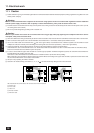
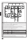
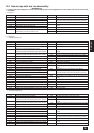
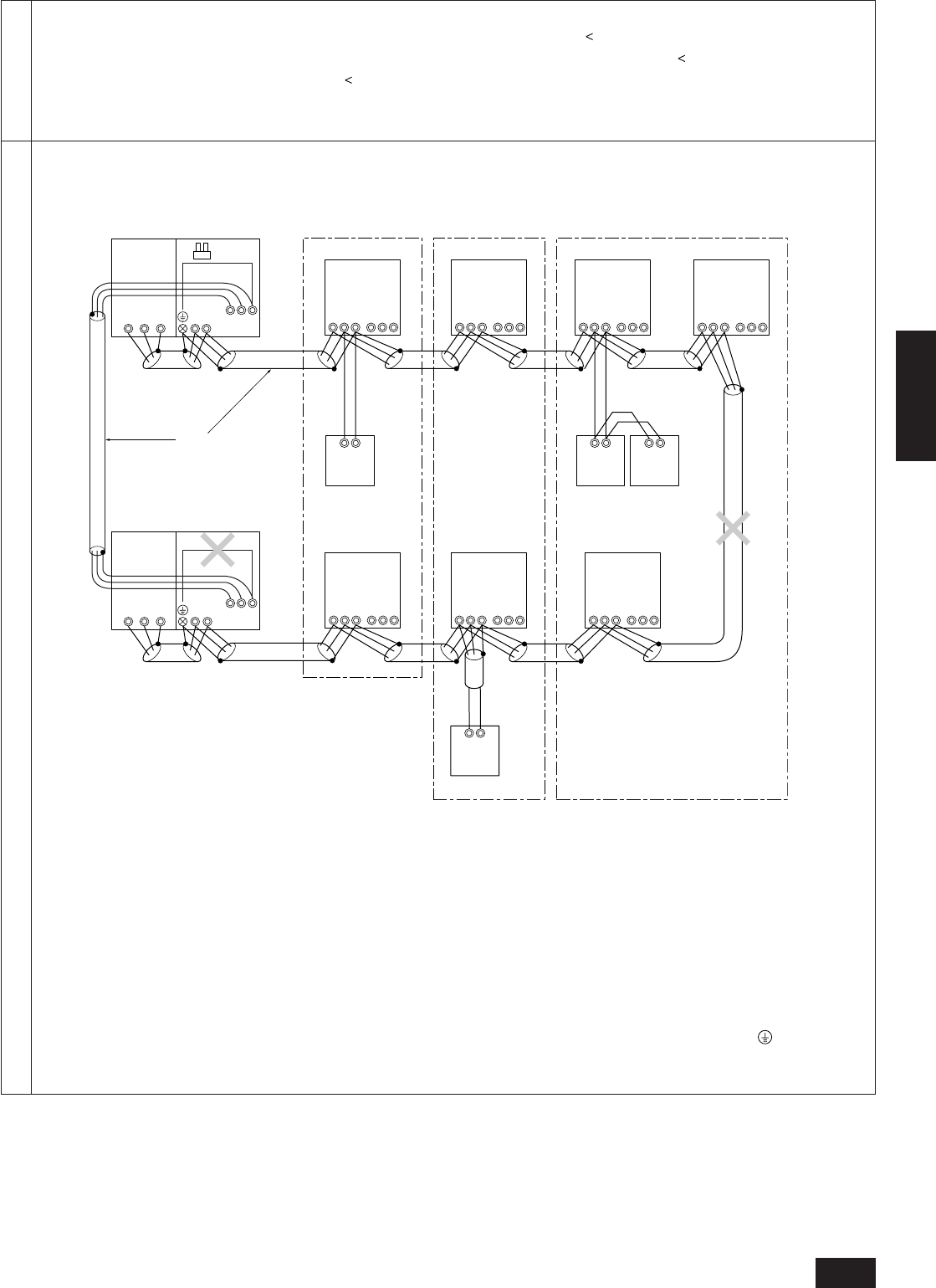
Shielded cable
Permissible length
• Length of wire to the most remote unit via the outdoor unit : L1+L2+L3+L4+L5+L6+L7+L9,
L1+L2+L3+L4+L5+L6+L8+L9
=
500 m (1.25 mm
2
)
• Length of wire to the most remote unit via the indoor system : L1+L2+L3+L4, L5+L6+L7, L5+L6+L8, L7+L8
=
200 m (1.25 mm
2
)
• Remote control wire length : r1, r2, r3, r4
=
10 m (0.5 to 0.75 mm
2
)
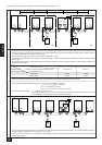
If the length exceeds 10 m, use 1.25 mm
2
wire and calculate the length of that portion (L8) as within the total
extended length and the length to the most remote unit.
Prohibited items
• Connect the S terminal of the centralized control terminal block (TB7) of one variable capacity unit only to the ground of the electrical
equipment panel.
• The transmission line terminal blocks (TB5) of indoor units (IC) connected to different cooling systems should not be connected together.
Note:
1. If there is one or more 200 or higher indoor units within the same cooling system, and the number of indoor units exceeds 16 units, a
transmission booster is necessary. (When a “PAR-F25MA Ver. F or subsequent version of remote control is used)
2. If there is not even one 200 or higher indoor unit within the same cooling system, and the number of indoor units exceeds 20 units, a
transmission booster is necessary. (When a “PAR-F25MA Ver. F or subsequent version of remote control is used)
* For details, see wire connection example C.