


30
ENGLISH
Group 1 Group 3 Group 5
(Sub remote
controller)
Shielded cable
M1 M2
M1M2 S
TB7
M1 M2 S
TB3
TB3
(51)
RC
IC
(02)
IC
M1M2 S
TB5
M1M2 S
TB5
(01)
IC
M1M2 S
TB5
123
TB13
123
TB13
123
TB13
IC
(03)
M1M2 S
TB5
123
TB13
IC
(07)
M1M2 S
TB5
123
TB13
(04)
L1
L8
r1
r4
L9
L2 L3 L4
L5 L6 L7
TB6
(101)
RC
TB6
(105)
RC
TB6
(103)
RC
TB6
(155)
CN40
OC
(54)
OS
M1 M2
M1M2 S
TB7
TB3
(52)
OC
r2
r3
M1 M2 S
TB3
(53)
OS
IC
M1M2 S
TB5
(05)
IC
M1M2 S
TB5
123
TB13
123
TB13
(06)
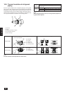
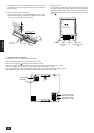
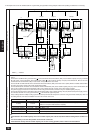
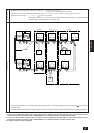
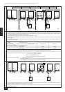
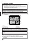
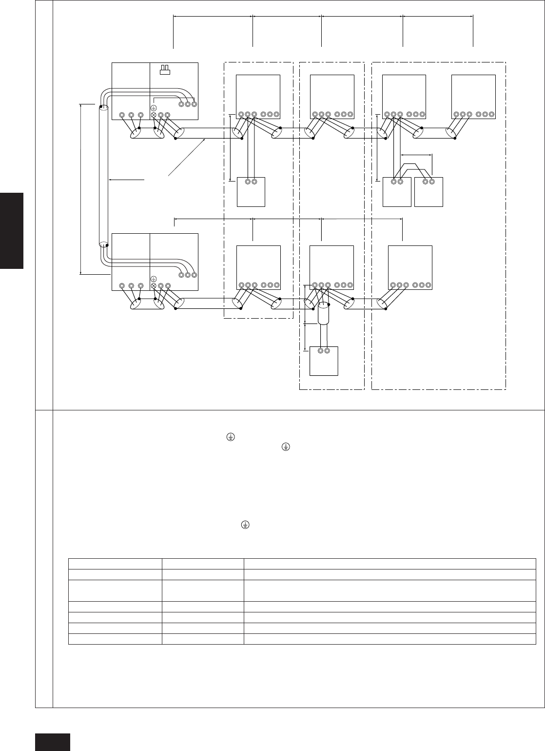
B. Example of the use of the shielded cable in a system with group operation among multiple outdoor units (Setting of addresses is necessary)
Example of transmission line wiring
Within ( ): Address
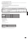
Wiring method, address setting method
a. Be sure to use shielded cable for wiring between the outdoor units (OC and OS) and indoor units (IC), between OC and OC and between IC
and IC.
b. Terminals M1 and M2 and the ground terminal of the transmission line terminal block (TB3) of each variable capacity unit (OC), terminals
M1, M2 and S of the transmission line terminal block (TB3) of the constant capacity unit (OS) and terminals M1, M2 and S of the
transmission line terminal block (TB5) of each indoor unit (IC) should be cross wired.
c. Connect the M1 and M2 terminals of the transmission line terminal block (TB5) of the indoor unit IC (Main) with the smallest address within
the same group to the remote control (RC) terminal block (TB6).
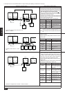
d. Connect terminals M1, M2 and S of the centralized control terminal block (TB7) of the variable capacity unit (OC) and the terminals M1, M2
and S of the centralized control terminal block (TB7) of the variable capacity unit (OC) of the other cooling systems.
e. The power supply connector on the main board can be changed from CN41 to CN40 for only one variable capacity unit (OC).
f. Connect the S terminal of the centralized control terminal block (TB7) of the variable capacity unit (OC) which had its power supply connec-
tor connected to CN40 in e to the ground terminal in the electrical equipment panel.
g. Group settings between multiple cooling systems should be performed after the power is turned on using the remote control (RC) units. For
the setting method, refer to the installation manual for the remote control unit.
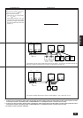
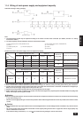
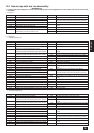
Unit Range Setting method
IC (Main) 01 to 50 Smallest address of all the indoor units (IC) in the same group
IC (Sub) 01 to 50
Address other than the IC (Main) of the indoor units in the same group. Use a number
which is in sequence with that of the IC (Main)
Main remote controller 101 to 150 Note 2 IC (Main) + 100
Sub remote controller 151 to 200 Note 2 IC (Main) + 150
Variable capacity unit 51 to 100 Note 1 The smallest address of the indoor units in the same cooling system + 50
Constant capacity unit 51 to 100
Notes 1, 3
Variable capacity unit address + 1
Note:
1. If the address of the variable capacity unit or the constant capacity unit is set at 100, set the address setting switch at either 01 or
50.
2. It is not necessary to set the 100’s position on the remote control unit.
3. If the addresses overlap with the variable capacity unit of other cooling systems, select a different unused address.