


36
ENGLISH
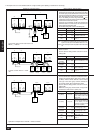
3. Remote controller
Check code Abnormality Check code Abnormality
6101 Unreadable response receiving error
6600 Duplicated unit address setting
6602 Transmission error (Transmission processor hardware
error)
6603 Transmission error (Transmission route BUSY)
6606 Transmission and reception error (Communication trou-
ble with transmission processor)
6607 Transmission and reception error (No ACK error)
6608 Transmission and reception error (No responsive frame
error)
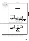
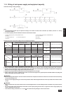
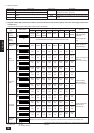
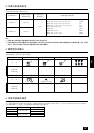
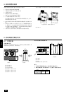
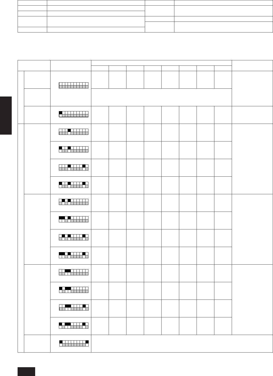
2 Diagnostic switch (SW1) and the service LED on multi-controller board of the variable capacity unit can be used to judge a malfunction
of outdoor unit.
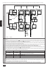
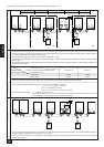
<Operation of self-diagnosis switch (SW1) and the service LED display>
Display at LED lighting (blinking)
Flag 1 Flag 2 Flag 3 Flag 4 Flag 5 Flag 6 Flag 7 Flag 8
A
B
C
12345678910
A
B
12345678910
Relay output
display 1
(Lighting)
Check
display 1
(Blinking)
Relay output
display 2
Check
indoor unit
Indoor unit
mode
Indoor unit
thermostat
Indoor unit
address
During
compres-
sor run
SV4
No.1
unit
No.9
unit
No.17
unit
No.25
unit
No.1
unit
No.9
unit
No.17
unit
No.25
unit
No.1
unit
No.9
unit
No.17
unit
No.25
unit
Compres-
sor 2
operations
SV5b
No.3
unit
No.11
unit
No.19
unit
No.27
unit
No.3
unit
No.11
unit
No.19
unit
No.27
unit
No.3
unit
No.11
unit
No.19
unit
No.27
unit
21S4
SV6
No.4
unit
No.12
unit
No.20
unit
No.28
unit
No.4
unit
No.12
unit
No.20
unit
No.28
unit
No.4
unit
No.12
unit
No.20
unit
No.28
unit
SV1
CH2, 3
No.5
unit
No.13
unit
No.21
unit
No.29
unit
No.5
unit
No.13
unit
No.21
unit
No.29
unit
No.5
unit
No.13
unit
No.21
unit
No.29
unit
52F
No.6
unit
No.14
unit
No.22
unit
No.30
unit
No.6
unit
No.14
unit
No.22
unit
No.30
unit
No.6
unit
No.14
unit
No.22
unit
No.30
unit
SV22/32
(Note:1)
No.7
unit
No.15
unit
No.23
unit
No.31
unit
No.7
unit
No.15
unit
No.23
unit
No.31
unit
No.7
unit
No.15
unit
No.23
unit
No.31
unit
Compres-
sor 1
operations
21S4b
No.2
unit
No.10
unit
No.18
unit
No.26
unit
No.2
unit
No.10
unit
No.18
unit
No.26
unit
No.2
unit
No.10
unit
No.18
unit
No.26
unit
Always
lighting
No.8
unit
No.16
unit
No.24
unit
No.32
unit
No.8
unit
No.16
unit
No.24
unit
No.32
unit
No.8
unit
No.16
unit
No.24
unit
No.32
unit
0000 to 9999 (Alternate display of address and error code)
Flag 8 always lights
at microcomputer
power ON
(Note:1) Type 500
only
SV5A and 5B are
closed with flag 1
Lights at emergency
stop in IC
Turns off by resetting
Lights at cooling
Blinks at heating
Turns off at stop/fan
Lights at thermostat
on Turns off at
thermostat off
A
B
12345678910
A
B
12345678910
A
B
12345678910
A
B
12345678910
A
B
12345678910
A
B
12345678910
A
B
12345678910
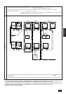
a Outdoor unit A ON
b Indoor unit B OFF
C At factory shipment
a
b
Self-diagnosing
item
SW1 setting
Displays in order the addresses (1 through 50) of all indoor units connected to the outdoor unit.
A
B
12345678910
A
B
12345678910
A
B
12345678910
* Turn SW4-2 of variable capacity unit off. If SW4-2 is on, constant capacity unit data will be
displayed.
A
B
12345678910
A
B
12345678910
A
B
12345678910
Remarks