


25
ENGLISH
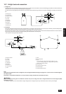
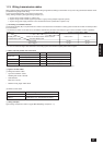
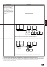
3. Connect indoor and outdoor units through the terminal block for trans-
mission lines (TB3). Outdoor units and connections to central control
systems go through the terminal block for centralized control (TB7).
When making an indoor/outdoor connection with shielded wiring, con-
nect the shield ground to the earth screw ( ). When making a cen-
tral control system connection with shielded wiring, use the terminal
block for centralized control (TB7).
When the CN41 power supply connector of an outdoor unit has been
replaced with a CN40, the shield terminal (S) for centralized control
(TB7) should also be connected to the earth screw ( ).
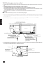
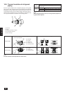
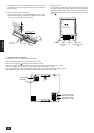
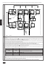
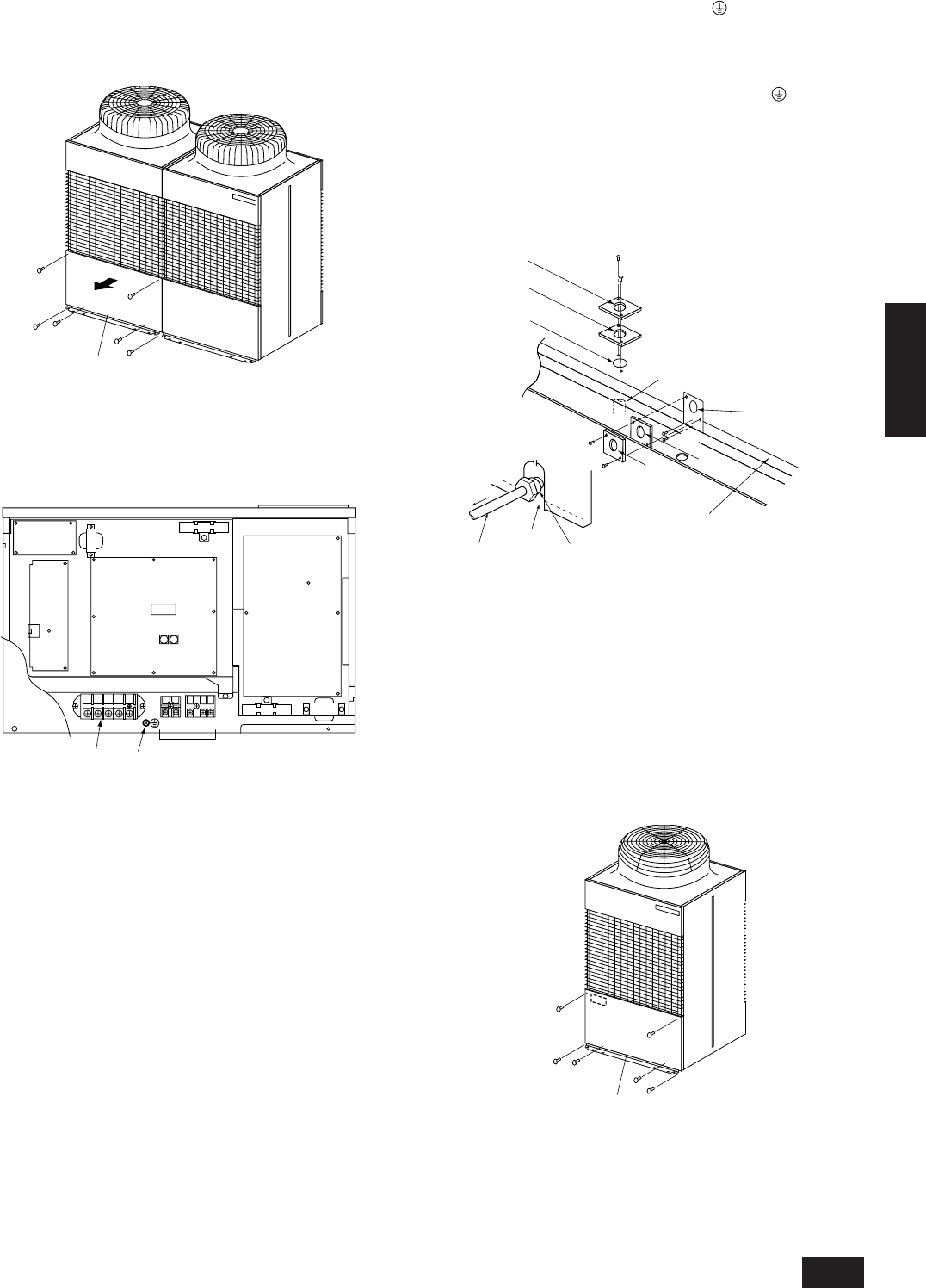
4. How to use the conduit mounting plate
(1) Conduit mounting plates (ø46, ø53, ø62) are being provided.
Select conduit mounting plate based on the outside diameter of con-
duit to be used and mount it as shown in the figure.
(2) Fix power source wiring to control box by using buffer bushing for
tensile force (PG connection or the like)
To prevent external tensile force from applying to the wiring connection
section of power source terminal block, use buffer bushing like PG
connection or the like.
knockout hole
Tensile force
A
D
A
F
G
E
B
C
B
A ø46 mounting hole
B ø53 mounting hole
C ø62 knockout hole
D For the connection of conduit at bottom
E ø62 mounting hole
F For the connection of conduit at front
G The front of outdoor unit
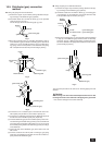
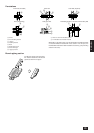
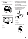
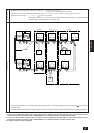
b. Constant capacity unit
1. The service panel is removed by removing the six screws at the top
and bottom and pulling it forward. (see figure below.)
Service panel
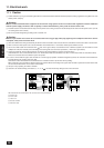
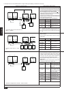
11.2. Control box and connecting posi-
tion of wiring
a. Variable capacity unit
1. Remove the total of six screws at the top and bottom, and remove
the service panel by pulling it forward. (see the figure below.)
A
A Service panel
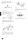
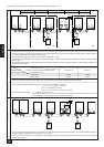
2. Remove the two screws on the left and right-hand of the base of the
control box and pull the overall cover downwards to detach it. (a dia-
gram with the control box cover removed is shown below.)
L1 L2 L3
TB1
TB7TB3
LD1
M1 M2M1 M2 S
N
F
J
B
CD A
E
GH I
A INV board
B MAIN board
C Ten position
D One position
E Address
F FANCON board
G Power source
H Earth screw
I Transmission line
J RELAY board