20
ENGLISH
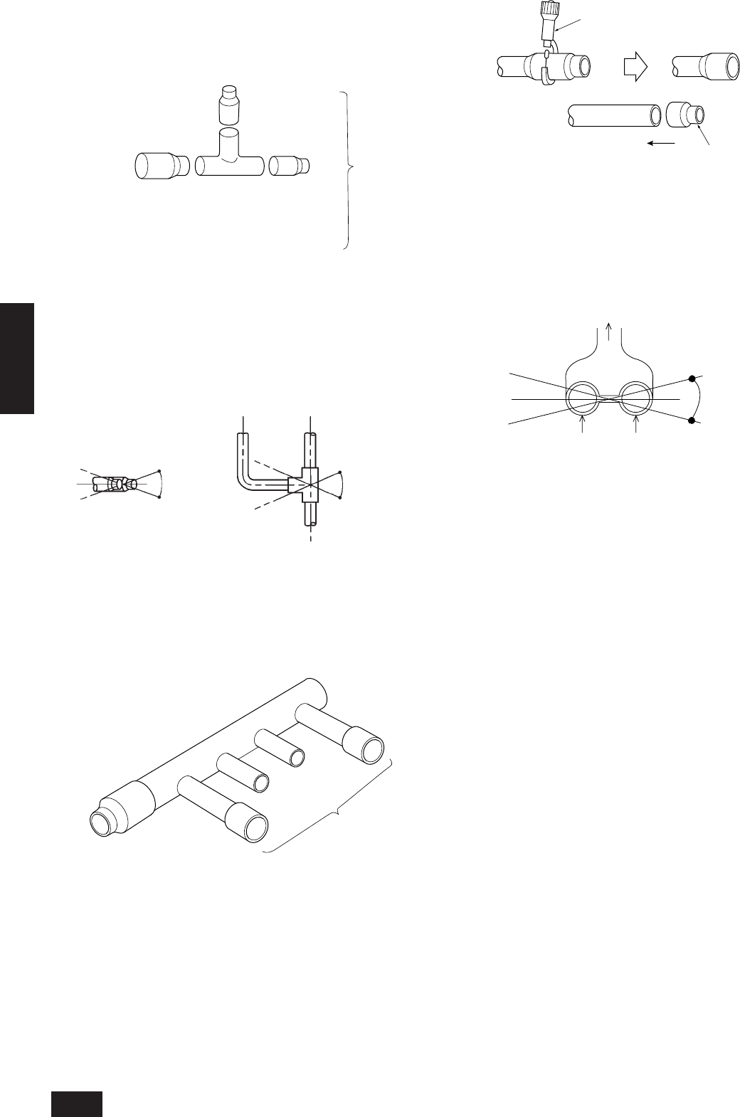
10.6. How to install branch pipe
For detail, please observe the instruction manual attached to the op-
tional refrigerant branch kit.
■ Joint
A To outdoor unit
B To branch piping or indoor unit
• Apart from the CMY-Y202-F and CMY-Y302-F gas side, there are no
restrictions on the posture for attaching joints.
• Ensure that the branch pipes for the CMY-Y202-F and CMY-Y302-F
gas side are attached horizontally or facing upwards (see the dia-
gram below.)
Horizontal Facing upwards
(Facing downwards is not possible)
• There is no limitation on the joint mounting configuration.
• If the diameter of the refrigerant piping selected by the procedures
described on pages
13
to
14
is different from the size of the joint,
match the sizes using a deformed joint. The deformed joint is included
with the kit.
■ Header
B
A
A To outdoor unit
B To indoor unit
• No restriction is applied to the mounting posture of the header.
• If the diameter of the refrigerant piping selected using the proce-
dures described on pages
14
and the size of the joint is different,
match the sizes using a deformed joint. The deformed joint is included
with the kit.
C
E
D
C Pipe cutter
D or
E Deformed joint
• When the number of pipes to be connected is smaller than the number
of header branches, install a cap to the unconnected branches. The
cap is included with the kit.
■ Distributer (liquid)
±15°
Variable
capacity unit
Field piping
Constant
capacity unit
• Mount the distributor (liquid, optional CMC-30A) so that it is within
±15° in relation to the horizontal plane (see figure above).
Within ± 15
degrees
Within ± 15
degrees
Within ± 15
degrees
B
A


