


GENERAL
mini HE --- Installation & Servicing
9
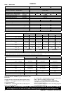
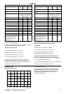
5 From vertical drain pipes or soil
pipes*
25 mm ( 1”) ***
6 From an internal or external corner
or to a boundary along side the
terminal
25 mm ( 1”) ***
7 Above adjacent ground, roof or
balcony level
300 mm (12”)
8 From a surface or a boundary
facing the terminal.
600 mm (24”)
9 From a terminal facing a terminal 1200 mm (48”)
10 From an opening in a car port (e.g.
door or window) into dwelling
1200 mm (48”)
11 Vertic ally from a terminal on the
same wall
1500 mm (60”)
12 Horizontal ly from a terminal on the
wall
300 mm (12”)
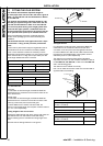
* If the terminal is within 150mm of any vertical soil or drain
pipe, an aluminium shield at least 400mm (15 3/4”) long
should be fitted equi---distant from the terminal and close to
the pipe.
*** Only 1 spacing down to 25mm is allowable per
installation.
Vertical Terminals
13 Above the roof pitch with roof
slope of all angles.
Above flat roof
300 mm (12”)
300 mm (12”)
14 From single wall face
From corner wall faces
600 mm (24”)
1000 mm (40”)
Twin Flue Applications
15 Centre distance between air inlet
and flue outlet ducts
120mm (5”) **
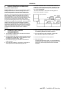
** Where the twin flue ducts are positioned at or near the above
minimum centres the wall sealing gaskets should be trimmed to
allow them to fit f lat to the wall. This should b e d o ne for both in-
side and outside wall gaskets
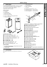
Terminals guards are available from boiler suppliers --- ask for
Tower Flue Guard, Model K6. In case of difficulty seek advice
from:
Grasslin UK Ltd.,Tower house, Vale Rise, Tonbridge,
Kent TN9 1TB Tel. +44 (0) 1732 359 888 Fax No. +44 (0)
1732 354 455 www.tfc---group.co.uk
IMPORTANT It is absolutely ESSENTIAL to ensure, in
practice, that products of combustion discharging from the
terminal cannot re---enter the building or any other adjacent
building through ventilators, windows, doors other sources of
natural air infiltration, or forced ventilation / air conditioning.
If this should occur the appliance MUST be turned OFF,
labelled as “uns afe” unt il corrective actio n t aken.
AIR SUPPLY
It is NOT necessary to have a purpose---provided air vent in
the room or internal space in which the boiler is installed.
Neither is it necessary to ventilate a cupboard o r
compartment in which the boiler is installed, due to the low
surface temperatures of the boiler casing during operation;
therefore the requirements of BS6798, Clause 12, BS 5440:2
and in IE I.S. 813:2002 may be disregarded.
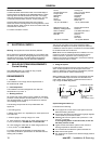
WATER CIRCULATION SYSTEM
The boilers are designed for connection to pressurised, fully
pumped, sealed water central heating systems ONLY. The
domestic hot water (DHW) calo rifier is incor porated within the
combi boiler and only requires co nnection to the mains water
supply.
Additional Pumps.
The boiler is supplied with an integral cir culating pump. If the
boiler is to be used in conjunction with any additional
circulating pumps, please c ontact the Technical Helpline for
advice on application.
IMPORTANT
A minimum length of 1m of copper pipe MUST be fitted to
both flow and return connections from the boiler before
connec tion to any plastic piping.
Ensure that the mains water supply pressure is adequate to
provide the required DHW flow rate. Refer to Table 1 on
page 4.
The central heating system should be in accordance with BS.
6798 and, in addition, for smallbore and microbore systems
BS. 5449.
The domestic hot water system should be in accordance with
BS. 5546 and BS. 6700.
Copper tubing to BS 2871:1 is recommended for water
carrying pipework and MUST be used for pipework carrying
potable water.
Any soldered joints on potable water pipework MUST NOT be
made with solder containing lead.
Ancillary pipework not forming part of the useful heating
surface should be lagged to prevent heat loss and any
possible freezing --- particularly where pipes run through roof
spaces or ventilated underfloor spaces.
Draining taps should be at least 1/2” BSP nominal size and
be in accordance with BS 2879.
WA TER TREATMENT
Central Heating
Antifreeze fluid, corrosion and scale inhibitor fluids suitable for
use with boilers having copper heat exchangers may be used
in the central heating system.
IMPORTANT
The application of any other treatment to this product
may render the guarantee of Caradon Ideal Limited
INVALID .
Caradon Ideal Limited recommend Water Treatment in
accordance with the Benchmark Guidance Notes on Water
Treatment in Central Heating Systems.
Caradon Ideal Limited recommend the use of Fernox , GE
Betz Sentinel or Salamander water treatment products, which
must be used in acc ordance with the manufacturers
instructions.
Notes.
1. It is most important that the correct concentration of the
water treatment products is maintained in accordance with
the manufacturers’ instructions.
2. If the boiler is installed in an existing system any unsuitable
additives MUST be removed by thorough cleansing.
BS 7593:2006 details the steps necessary to clean a
domestic heating system.
3. In hard water areas, treatment to prevent lime scale may be
necessary --- however, the use of artificially softened water is
NOT permitted.
4. Under no circumstances should the boiler be fired before
the system has been thoroughly flushed.