


SERVICING
mini HE --- Installation & Servicing46
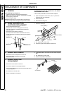
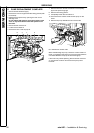
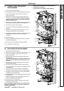
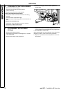
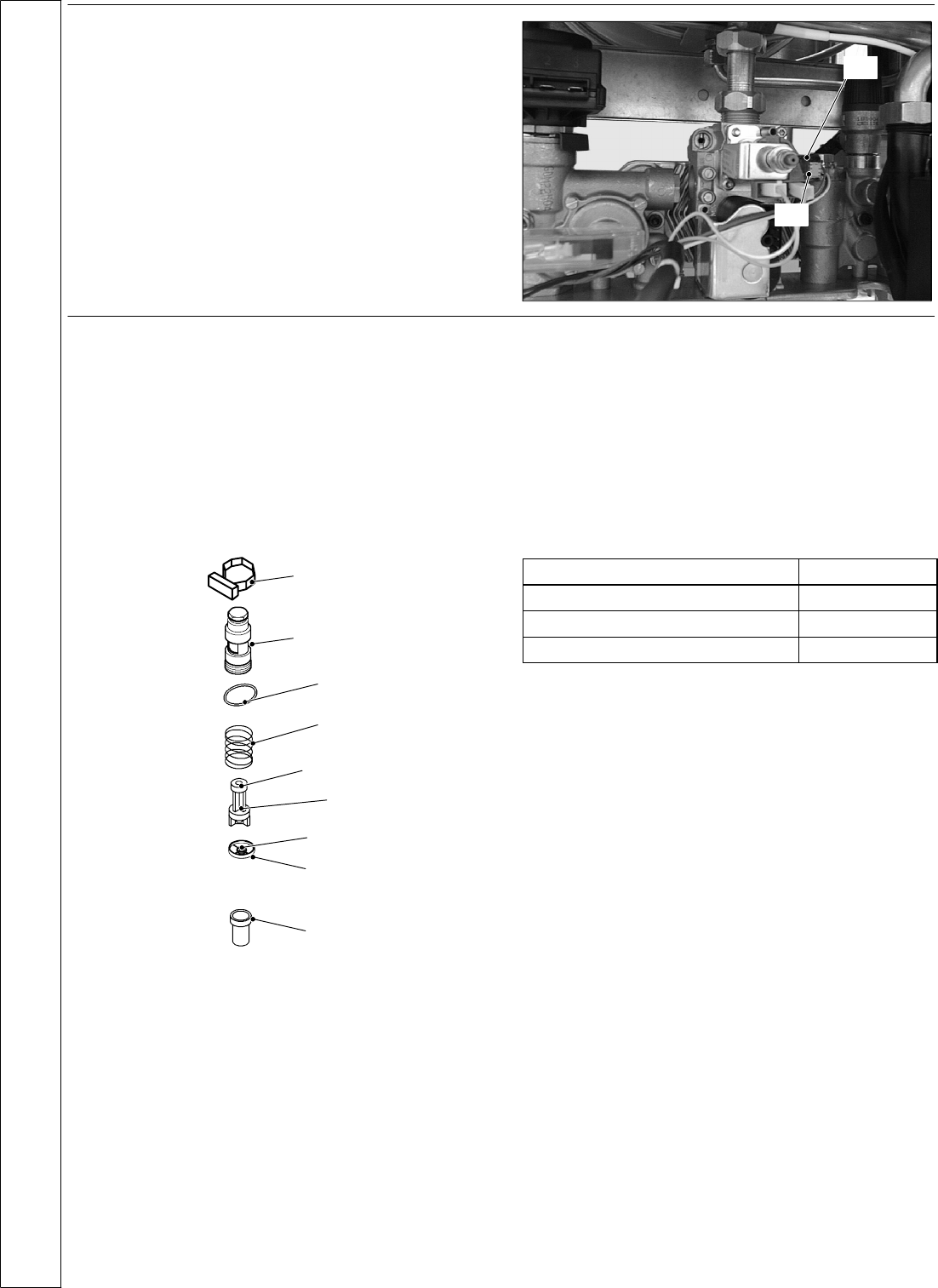
65 DHWFLOWSWITCHREPLACEMENT
1 Disconnect the electrical supply .
2 Remove the front panel of the case (refer to frame 42).
3 Disconnect the connector A and remove the s witch B by
delicately levering it upwards with a screwdriver.
4 R eplace the switch and re---assemble in reverse order
A
B
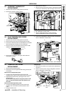
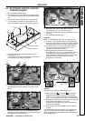
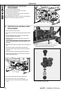
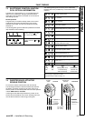
66 DHW FILTER AND FL OW LIMITER
REPLACEMENT
1 Disconnect the electrical supply .
2 Remove the front panel of the case and empty the DHW
circuit.
3 Remove the flow switch A (see frame 65).
4 Unscrew the body C and extract the flow switch group.
5 To remove the filter B from the flow switch group separate
it from the threaded ring by levering it.
6 Re---assemble in reverse order.
A --- f low sw itc h
B --- f ilte r
C--- body
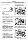
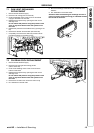
Magnetic ring
Float
Spring
Flow l i miter
Threaded ring
O --- r in g
Flow limiter
The mini HE C24 model is factory fitted with a 10 litre/min.
flow limiter.
The mini HE C28 model is factory fitted with a 12 litre/min.
flow limiter.
The mini HE C32 model is factory fitted with a 14 litre/min.
flow limiter.
Tab le 1 1
Nominal flow rate (litres/min)
Colour
10 Yellow
12 Brown
14 Pink
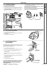
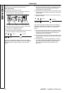
To install the threaded ring with the flow limiter:
1 Disconnect the electrical supply .
2 Remove the front panel of the case and empty the DHW
circuit.
3 Remove the flow switch A (see frame 65).
4 Remove the flow switch group (see frame 66 above)
5 Unscrew the threaded ring and remove it from the body C.
6 Extract the flow limiter.
7 F it the correct colour coded limiter (see Table 11 above)
and screw the threaded ring tight into the body C.
8 Re---assemble in reverse order.
SERVICING