


FAULT FINDING
mini HE --- Installation & Servicing
51
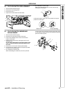
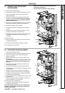
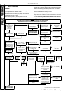
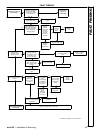
75 ELECTRONIC CONTROL/IGNITION
P.C.B. OPTICAL INFORMATION
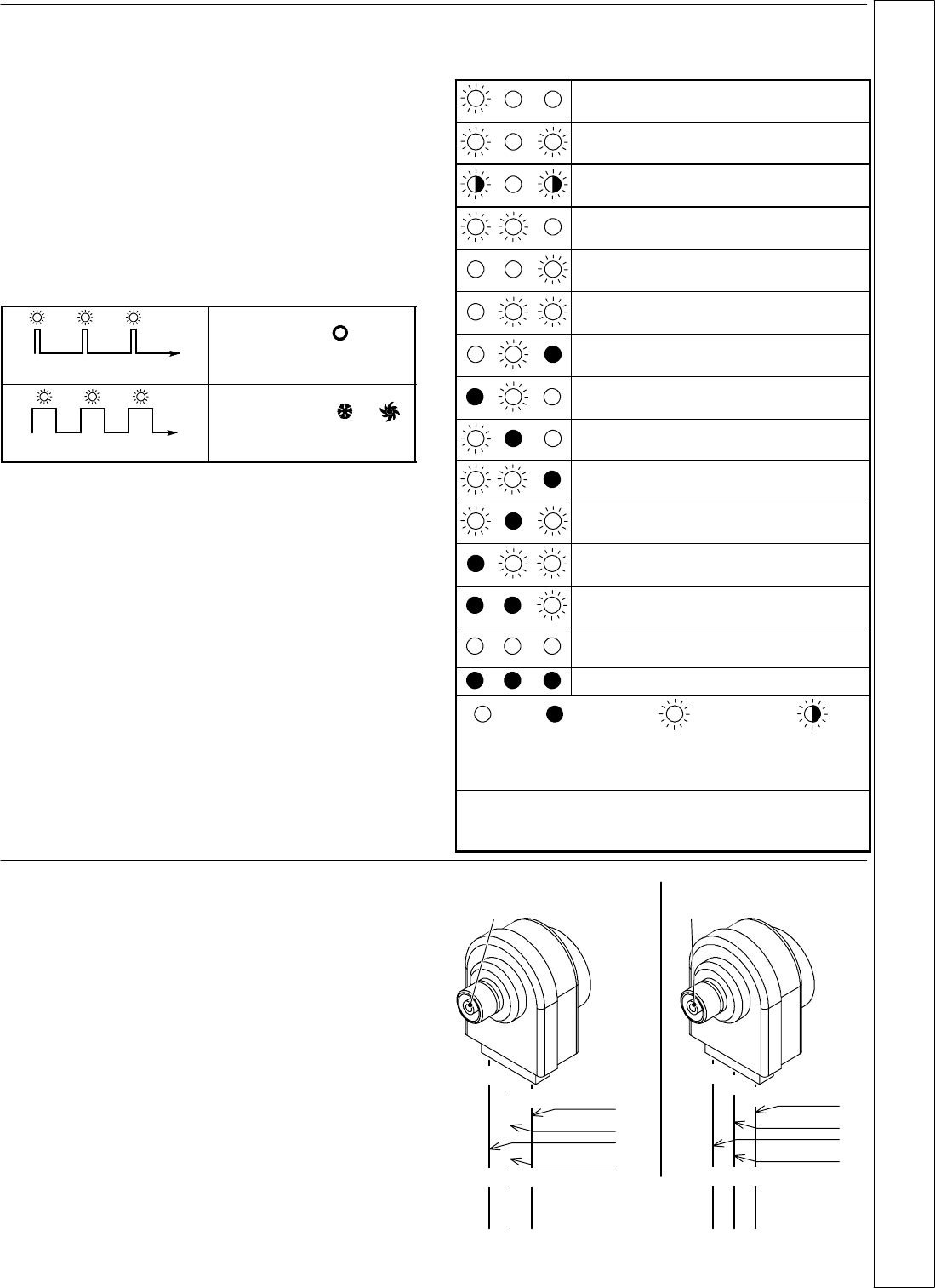
The electronic c o ntro l/ignition p.c.b. is provided with three
lamps (L.E.D. indicators) A, that give optical information
during the normal operation of the boiler or for service and
fault fiinding purpose.
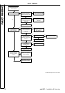
Normal operation
The green lamp on the left is directly visible on the control
panel fascia and it gives information during the normal
operation of the boiler. The other two lamps are normally
switched off.
The following table gives the relationship between the visible
lamp indication and its meaning.
Boiler in stand---by condition.
(function control in position).
A short pulse every 4 seconds
Anti---freeze syst e m active.
Boiler ON condition
(function control in or
p
o
s
i
t
i
o
n
)
1secondON1secondOFF
position)
The following table gives a summary of the relationship
between each of the possible lamp combinations and their
meaning.
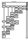
Normally operating boiler
C.h. operation
D.h.w. operation
F rost protect operation
D.h.w. operation
Excessive temperature on primary circuit
Faulty c.h. temperature probe NTC
Faulty d.h.w temperature probe NTC
Faulty flue temperature probe NTC
Faulty primary circuit
(no water or absence of flow)
Faulty air pressure switch
Lack of burner ignition (no ignition signal from
the full seqence ignition device)
Overheat thermostat lock out
Flue temperature probe NTC lock out
Lack of power supply or fauly electronic
control p.c.b. *
Faulty Electronic control/ignition p.c.b.. *
Lamp
OFF
Lamp
ON
Flashing lamp, alone
or simultaneously
with an other lamp.
Flashing lamp,
alternate with
another lamp.
* These conditions are normal only for a short time when the
power supply is applied to the boiler.
If permanent they indicate a faulty p.c.b.
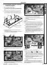
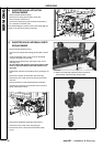
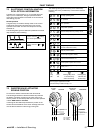
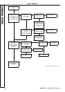
76 DIVERTER VALVE ACTUATOR
SPINDLE POSITION
To remove the diverter valve actuator refer to frame 69.
The following illustrations indicate the relationship between
the electric command coming from the main control p.c.b.
and the position of the brass spindle when the boiler operates
in either DHW mode or CH mode.
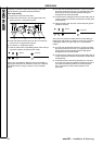
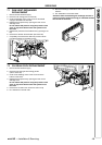
In both figures the relationship between the position of the
actuator and the resistance of the motor windings (the motor
must be disconnected from the wiring) is also given.
bn = brown
bu = blue
bk = black
230 V
0V
Spindle
visib le
Open circuit
9,4 Kohm
bk
bn
bu
3
1
2
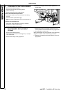
0V
230 V
Spindle fully
retracted
Open circuit
9,4 Kohm
bk
bn
bu
3
1
2
CH mode DHW mode
FAULT FINDING