


SERVICING
mini HE --- Installation & Servicing40
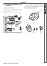
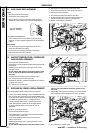
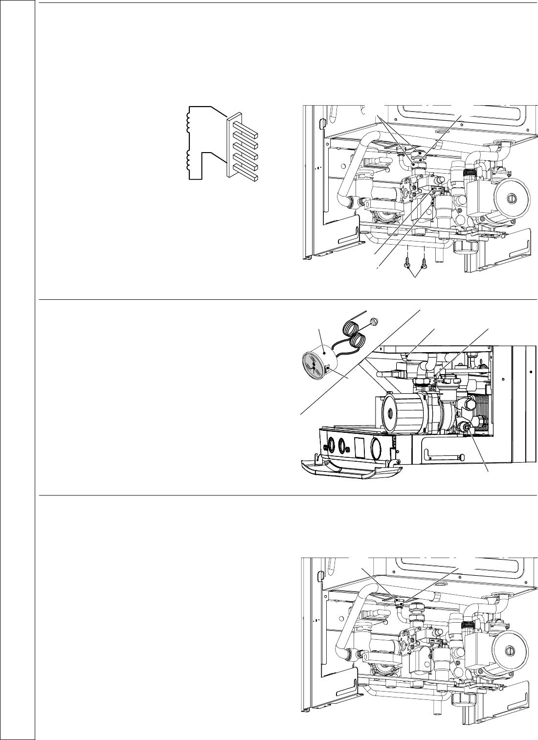
55 GAS V ALVE REPLACEMENT
Check
1 Disconnect the electrical supply .
2 Remove the front casing panel.
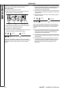
3 Disconnect the connector A and check the electrical
resistance of the coil referring to the following diagram
O n --- of f o pe r a to r
approx. 4 180 Ω*
* at ambient temperature.
4 If the resistance of the coil is different from the value
stated by ±10% or greater, replace the unit as desc ribed
below.
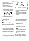
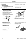
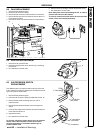
Replacement
5 Turn off the gas supply at the gas service cock and
disconnect the electricity supply.
6 Remove the front casing panel (refer to frame 42).
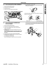
7 Disconnect the connectors A and B.
8 Disconnect the earth wiring from the gas valve.
9 Unscrew the connectors C and remove the pipe D
10 Unscrew the inlet connector.
11 Unscrew the screws E and remove the valve.
12 Fit the new gas valve in reverse order ensuring new
gaskets are fitted and check for gas t ightness.
13 Chec k the operation of the boiler.
B
C D
E
A
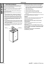
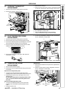
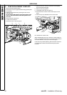
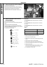
56 WATER TEMPERATURE ---PRESSURE
GAUGE REPLACEMENT
1 Disconnect the electrical supply .
2 Remove the front and right hand side casing panels (refer
to frame 42).
3 R elease system pressure by opening the main circuit
drainage cock A
Do not release CH pressure using the pressure relief
valve. It may cause debris within the system to foul
the valve.
4 Remove the fork B and the probe holder spring C.
5 Pull out the control panel (see frame 30).
6 Squeeze the tabs D to release the temperature---pressure
gaugeEandremoveit.
7 Re---assemble in reverse order.
C B
E
D
A
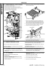
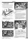
57 EXPANSION VESSEL REPLACEMENT
If the CH expansion vessel is faulty, there are 2 options:
A If it has a punctured diaphragm, but is otherwise leak free,
thanitcanbeleftinplaceandanewvesseladdedtothe
return side of the system, external to the boiler, provided it
is of adequate capacity and pre---charge pressure.
B If there is at least 400 mm (16”) cle arance above the
boiler, the expansion vessel can be changed without
removing the boiler (rear exit flues will have to be
disturbed).
For option B, proc eed as follows:
1 Disconnect the electrical supply .
2 Gain access to the controls area by removing the boiler
front panel (refer to frame 42).
3 Close off the isolating cocks of the CH circuit at the
bottom of the boiler.
4 R elease system pressure by opening the main circuit
drainage cock.
Do not release CH pressure using the pressure relief
valve. It may cause debris within the system to foul
the valve.
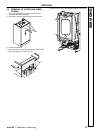
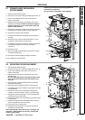
5 Completely unscrew the connection A, the locknut B and
remove the expansion vessel from the top of the boiler.
AB
6 Re---assemble in reverse order.
SERVICING