


INSTALLATION
mini HE --- Installation & Servicing
30
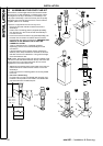
35 TO ADJUST PRESSURES
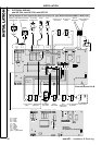
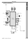
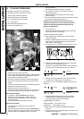
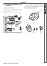
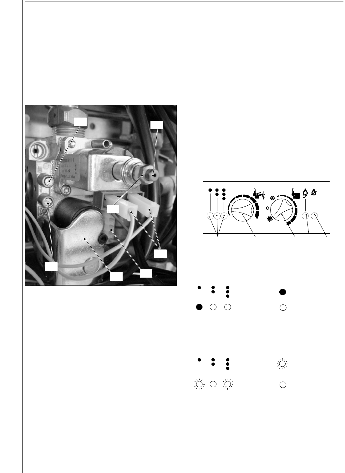
Nomenclature of the parts on the gas valve
H Modulation operator’s electric connectors
I Minimum gas pressure adjustment
J Maximum gas pressure adjustment
K On---off operators electric connector
L On---off operators
M Gas valve inlet pressure test point
N Burner pressure test point
J
H
I
M
N
K
L
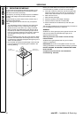
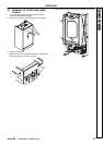
1 Remove the front panel of the case.
2 Open the gas valve inlet pressure test point M at the valve
input, connect a suitable pressure gauge and chec k the
gas pressure of the supply network.
3 Remove the gauge and close the pressure test point M.
4 Open the burner pressure test point N and connect the
gauge.
5 Remove the protection cap from the mechanical pressure
adjustment components (I and J)
6 Start the boiler at its maximum power.
Operate the boiler in DHW mode or ensure that the boiler
is not range rated if the test is carried out in CH mode.
Maximum valve setting
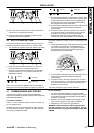
7 If necessary, rotate the maximum gas pressure
adjustment J using a spanner until you obtain the
required pressure as indicated on Table 1 at page 4
(burner pres sure).
By rotating clockwise the pressure increases.
Minimum valve setting
8 Tur n the boiler off and disconnect one of the two
connectors H.
9 Start the boiler and if necessary, rotate the minimum gas
pressure adjustment I using a spanner until you obtain the
required pressure as indicated on Table 1 at page 4
(burner pres sure).
By rotating clockwise the pressure increases.
10 Turntheboileroffandre---connectthewiretothe
modulating operator.
11 Start the boiler and check again the maximum gas
pressure setting.
12 Turn t he boiler off and disconnect the gauge and clo se the
gas valve outlet pressure test point N
Important: after the gas pressure checks and any
adjustment operations, all of the test points must be
sealed and replace the adjustment protection cap.
Ignition rate adjustment
1 Turnontheboiler.
2 Check that the boiler lights up uniformly and adjust the
ignition gas pressure, if necessary.
To adjust the ignition gas pressure:
3 Open the gas valve outlet pressure test point N and
connect the gauge.
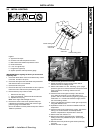
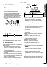
4 Rotate the radiator temperature control C as indicated in
the next figure and ensure that the room thermostat, if
fitted, is set to “heat demand”.
5 Run the boiler in c.h. mode (do not open any d.h.w. tap)
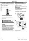
CA DEB
6 Press and hold the reset button D for about 10 seconds
until the lock---out signal light E blinks.
7 The lamps A should give the indication o f the next figure ;
ifnotthenpresstheresetbuttonDuntilyouobtainit.
Where:
Lamp ON
Lamp OFF
8 Press and hold the reset button D for about 5 seconds
until the lock---out signal light E is switched off.
The boile r runs in c.h. mode and the lights A give the follow
indication:
Where: Flashing lamp, alone
or simultaneously with
an other lamp.
Lamp OFF
9 Rotate the DHW temperature control B on a position
corresponding to an adequate ignition pressure. By
rotating clockwise the pressure increases.
Suggested ignition pressures:
Natural gas G20 --- 6 (2,4) mbar (in w.g.)
Propane G31 --- 13 (5,3) mbar (in w.g.)
10 Make a note of the position of the DHW temperature
control B.
11 Turn the boiler off and on positioning the main switch C as
indicated in the next figure.
INSTALLATION