


mini HE
mini HE C24 G.C. appliance No. 47---348---38
mini HE C28 G.C. appliance No. 47---348---39
mini HE C32 G.C. appliance No. 47---348---41
Destination countries: GB, IE
INTRODUCTION
mini HE are wall mounted, room sealed, condensing, low
water content combination gas boilers featuring full sequence
automatic spark ignition and fan assisted combustion.
SAFETY
Current Gas Safety (Installation & Use)
Regulationsorrulesinforce
In your own interest, and thatof safety, it isthe law that thisboiler
must be installed by a CORGI registered installer o r in IE a
competent person, in accordance with the above regulations.
It is essential that the instructio ns in this boo klet are strictly
followed, for safe and economical operation of the boiler.
ELECTRICITY SUPPLY
Theappliancemustbeefficientlyearthed.
Supply 230 V 50 Hz. The fusing should be 3 A.
Connection must be made i n a way that allows complete
isolation of the electric al supply, suc h as a double pole s witch,
having a 3 mm (1/8”) co ntact separ ation in both poles, or a
plug and soc ket serving only the boiler and syst em controls.
The means of isolation must be accessible to the user after
installation.
IMPORTANT NOTES
F This appliance must no t be operated without the casing
correctly fitted and forming an adequate seal.
F If the boiler is installed in a compartment then the
compartment MUST NOT be used for storage purposes.
F Under no circumstances should any of the sealed
components on this appliance be used incorrectly or
tampered with.
F If it is known or suspected that a fault exist on the boiler
then it MUST NOT BE USED until the fault has been
corrected by a CORGI registered installer or in IE a
competent person.
MINIMUM CLEARANCES
Clearances of 200 mm (7 7/8“) above and below, 25 mm (1“)
at left, 50 mm (2“) at right and 450 mm (17 3/4“) at the front of
theboilercasemustbeallowedforservicing.
After installation the following clearances are allowable during
use, providing the encasing parts are removeable for servicing:
The bottom clearance can be reduced to 20mm (3/4”).
The front clearance can be reduced to 50mm (2”).
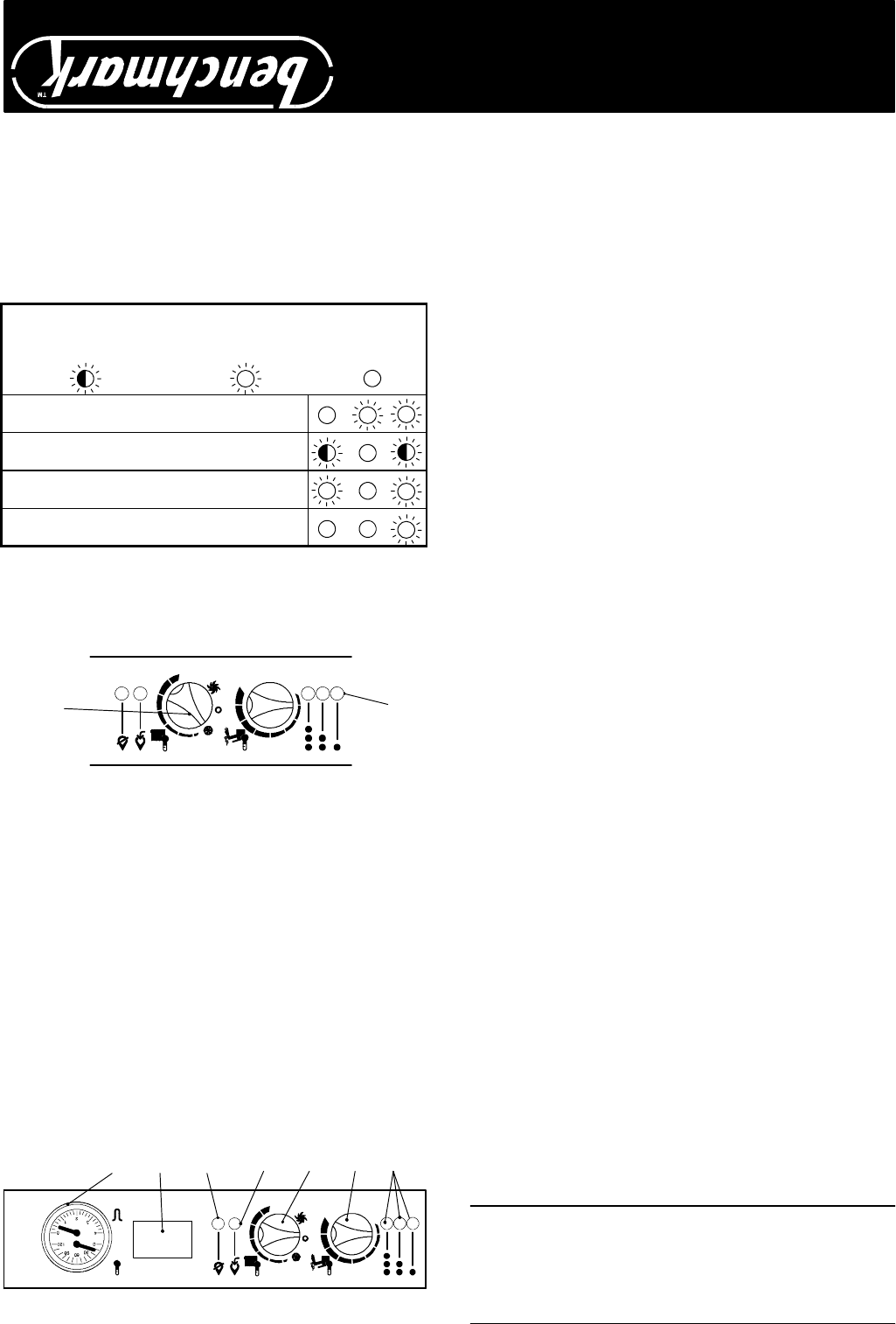
BOILER CONTROLS
BCD EF
G
A
A Appliance operation lights
B Domestic hot water temperature control
C Main switch and radiator temperature control
D Boiler reset button
E Lock---out signal lamp
F Programmer (optional)
G System pressure and temperature gauge
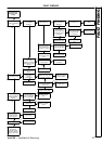
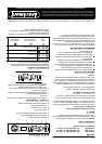
TO LIGHT THE BOILER
1 Check that the valves located in the lower part of the boiler
are open.
2 Switch the el ectricity supply on.
The appliance operation light A will flash every 4 seconds
(stand---by condition).
3 If the boiler is to be used for CH and DHW position the
main switch as in the following illustration.
The appliance operation light A will flash every 2 seconds
(operating boiler).
C
A
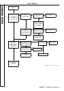
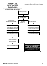
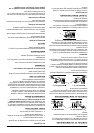
DIAGNOSTIC LIGHTS
The following table gives a summary of the relationship
between each of the possible light combinations and their
meaning during normal operaion of the boiler
Normally operating boiler
CH operation
DHW operation
F rost protect operation
Lamp
OFF
Flashing lamp, alone
or simultaneously
with an other lamp.
Flashing lamp,
alternate with
another lamp.
If the lights sequence observed on the boiler is not incl uded
above then a fault is indicated.
Reference should be made to the Installation Instructions or
consult a CORGI registered installer.
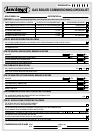
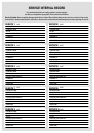
THE BENCHMARK SERVICE INTERVA L RECORD MUST BE COMPLETED AFTER EACH SERVICE
Caradon Ideal Limited is a member of the Benchmark initiative and fully supports the
aims of the programme. Benchmark has been introduced to improve the sta ndards of
installation and c ommissioning of central heating systems in the UK a nd to e ncourage
the regular servicing of all central heating systems to ensure safety and efficiency.
All CORGI registered installers carry a CORGI ID card, and have a registration number. Both should be record ed in the Benchmark
Commissioning Checklist. You can check your i nst aller by calling CORGI direct on 01256 372300.