


SERVICING
mini HE --- Installation & Servicing 43
62 ELECTRONIC CONTROL/IGNITION
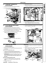
PCB REPLACEMENT
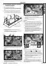
1 Disconnect the electrical supply .
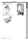
2 Gain access to the controls area by removing the boiler
front panel and pulling the control panel (refer to frame
30).
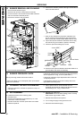
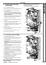
3 Remove the screws A and remove t he service panel
4 To gain access to the electronic control/ignition p.c.b.
remove the screws B and remove the control panel lid.
B
A
Control panel lid
Service panel
B
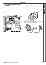
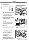
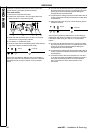
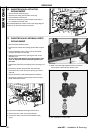
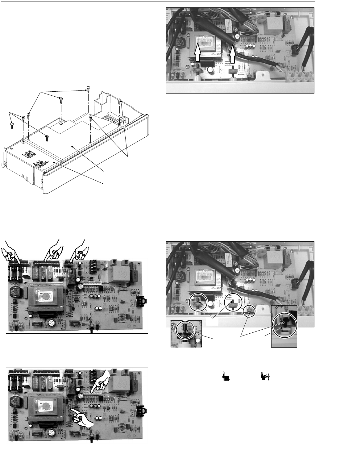
5 R emove all the wiring connected to the electronic
control/ignition p.c.b.
To disconnect the connectors indicated, delicately flex the
hook present on one side of each soc ket.
6 To dis connect the connect ors indicated in the next figure,
delicately press the hook present on one side of each
socket.
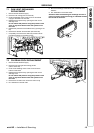
7 Remove the spindles of the CH and DHW temperature
adjustment knobs by delicately pulling them with pliers in
the direction shown by the arrows.
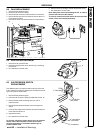
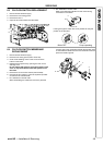
8 Unscrew the four screws that hold the elec tro nic
control/ignition p.c.b. on to the control panel.
9 Remove it by lifting its rear edge and freeing it from any of
the wiring.
10 Re---assemble in reverse order.
Important
When re---assembling the electronic control /ignition p.c.b.:
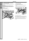
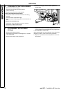
11 Fit the p.c.b. into the control panel by first inserting the
front lower edge under the control knob shafts. Lower the
rear edge and ensure that no wir ing i s trapped beneath.
12 Insert the spindles in the control panel knobs until the
notch C reaches the pote ntiometer edge. It is not
necessary to force them in the knob.
13 While tightening the scre ws that fix the electronic
control/ignition p.c.b. on the control panel, keep the p.c.b.
towards the control panel fascia making sure of the
contact between the boiler reset button D and the tab E.
Replace the wir ing connec tions ensuring correct
engagement in the sockets
C
C
D
E
Attention
After installing the electronic control/ignition p.c.b.:
14 Make sure the CH (
)andDHW( ) temperature
adjustment knobs can move freely for the complete
range. If not, remove the spindle again as des cribed at
step 7, turn the knob half a turn and re---insert the spindle.
15 Operat e the boiler and clos e the gas inlet cock so that the
boiler goes into the safety lock---out state.
V erify the correct operation of the boiler reset button by
pressing and releasing it.
16 Open the gas inlet cock and check the boiler operates
correctly.
The replace ment PCB is supplied pre---set for Nat ural Gas
and an anti cycling time of 3 minutes. If the install ation
requires adjustment of these settings refer to frames 35 and
36 for t he procedures
SERVICING