


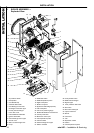
INSTALLATION
mini HE --- Installation & Servicing
22
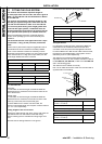
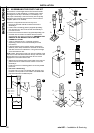
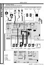
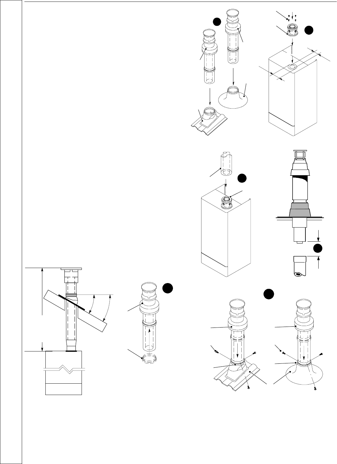
22 ASSEMBLING THE ROOF FLUE KIT
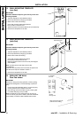
Determine the c orrect height that the flue should terminate
above the roof. If after calculating or measuring the overal l
flue height from the top of the boiler, it is necessary to cut
both pipes of assembly A, then ensure they are cut equally
leaving the inner flue tube longer than the outer air tube as
supplied. (Refer to No. 6 below)
Ensure the cut pipe ends are free from any burrs.
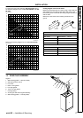
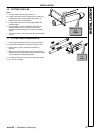
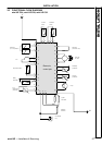
1 Ensure the flue seal collar B is located onto the flue
assembly A.
2 Position the roof flashing plate D (supplied separately)
overtheholecutintheroofandinsertflueassemblyA
from the roof end.
3 Push fit the vertical connector E (supplied separately) into
the boiler flue connection and retain with the screws F
(supplied with the vertical connector kit). ENSURING THE
GASKETS IN THE BOILER FLUE OUTLET ARE
CORRECTLY FITTED.
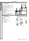
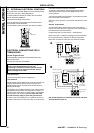
4 “Push” fit extension duct J (if required (supplied
separately)) and the roof flue kit assembly A into the
connector E.
5 If the last extensio n duc t requires cutting, measure t he
distance (outer ducts) between the duct and the terminal
and add 100 mm to this dimension. This gives the length
of the last extension duct.
NOTE. Check thepositionoftheinnerflueductrelativetothe
outer duct on the assembled extension duct(s) and ensure the
terminal flue duct is cut longer than the air duct to ensure
enga gement in the final flue duct seal.
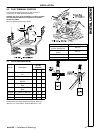
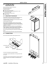
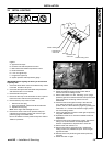
6 S lide down and position the flue seal collar B over the roof
plateDandsecureitwiththethreescrewsCtotheflue
assembly A.
7 Finally ensure the roof flashing plate D is correctly sealed
to the roof.
8 Flue over 3 meters long.
For flues over 3 m long a conensate drain and trap must
be fitted. The trap must be connected to a suitable waste
pipe. See frame 9 for available trap kit.
1
min 16
o
max 41
o
MAX LENGTH:
C24 --- 8.5 m
C28 --- 8.5 m
C32 --- 6 m
A
B
2
Ø 60
Ø 100
3
A
A
D
D
E
F
4
5
E
J
6
C
D
C
AA
B
B
INSTALLATION