


INSTALLATION
mini HE --- Installation & Servicing
24
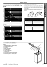
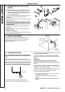
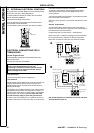
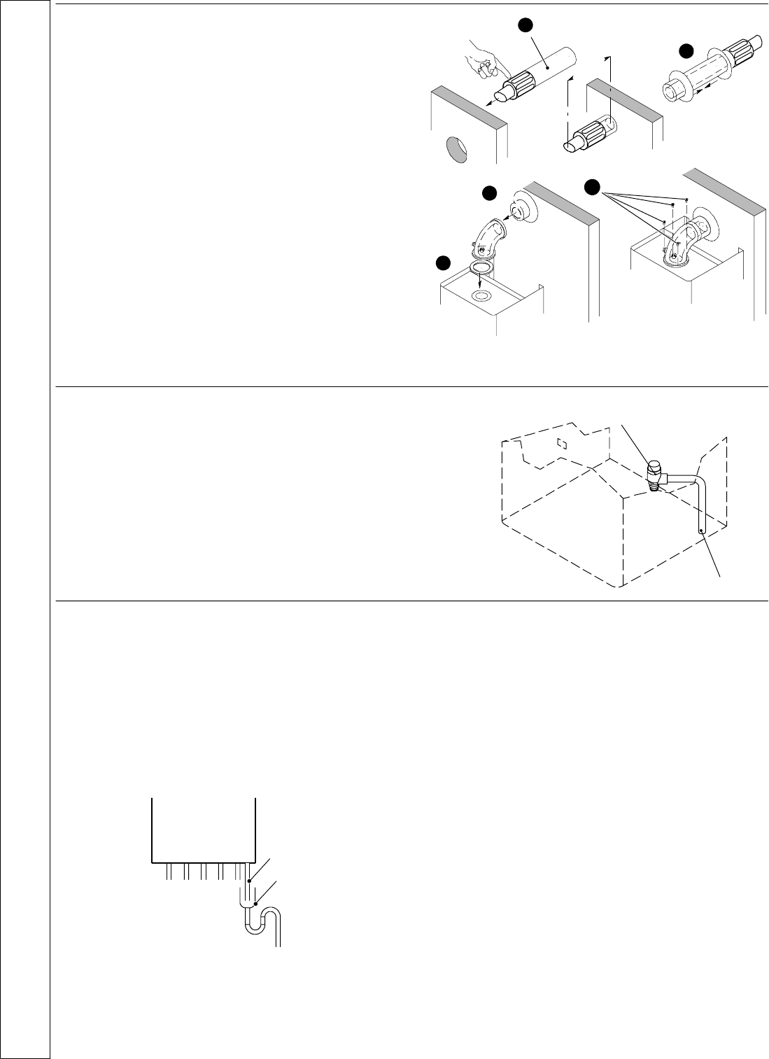
26 CONNECTING THE FLUE TO THE
BOILER
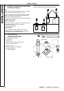
Note. Beforefittingtheflueturretfillthecondensatetrapor
siphon trap within the boiler by pouring a cupful of
water into the flue outlet. Take care to ensure that the
water is only poured into the flue outlet, and does not
spill into the boiler casing.
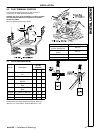
1 Insert the flue assembly through the prepared hole in the
wall (ensuring the 145mm minimum dimension is
maintained).
2 Fit the inner (plastic) and outer (rubber) wall gaskets to the
flue terminal pipe.
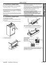
3 Locate the gasket and flue turret on the top of the boiler.
CHECK THAT THE FL UE SEAL LOCATED IN THE TOP
OF THE RECUPERATOR IS SECURE AND GIVING AN
EFFECTIVE SEAL.
4 Locat e the flue into the turret and push to ensure full
engagement.
5 Secure the flue turre t on top of the boiler using the four
screws provided.
6 Fluesover1meterlong.
Fix the flue support bracket to the wall, using the two wall
plugs and wood screws provided.
2
1
3
4
145
2
5
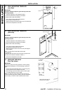
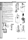
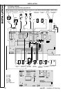
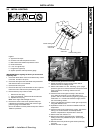
27 SAFETY VALVE DRAIN
The discharge pipe should be positioned so that the
discharge of water or steam cannot cr eate a hazard to the
occupants of the premises or damage to electrical
components and wiring.
Pressure
Discharge pipe
relief valve
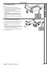
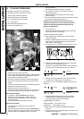
28 CONDENSA TE DRAIN
Refer also to the British Gas document: “Guidance Notes
for the installation of Domestic Gas Condensing Boilers”
(1989).
The condensate drain provided on the boiler must be
connected to a drainage po int, preferably within the buil ding.
The boiler includes a trap that prevents combustion products
entering the drain. However an additional trap with a seal of at
least 75 mm and an air break between the traps is required if
the condensate drain pipe is connected to sanitary pipework.
Condensate drain
Additional trap
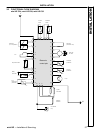
The length of the condensate pipe should be kept at
minimum and must be arranged so that obstruction (e.g.
through freezing) of external drainage pipework does not give
rise to spillage within the dwelling.
If a part of the drainpipe runs externally this par t should be
kept as short as possible and protected to reduce the risk of
freezing.
IMPORTANT
If excessive external pipework cannot be avoided an
additional condensate removal pump (available as an
option) and insulation are recommended to prevent possible
freezing.
The drain outlet on the boiler is a 25 mm o.d. plastic pipe.
This size must not be reduced below 21.5 mm o.d. (standard
overflow pipe) in any part of its length.
All pipework and fittings in the condensate drain system must
be made of plastic. No other materials may be used.
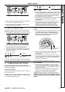
To avoid condensate being trapped:
--- the drainpipe should be run with a fall of at least 2.5û (45
mm/m) away from the boiler;
--- the number of bends and joints should be kept at
minimum;
--- the drainpipe should be adequately fixed to pevent pipe
sagging.
INSTALLATION