


INSTALLATION
mini HE --- Installation & Servicing
32
38 GENERAL CHECKS
Make the following checks for correct operation:
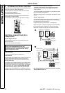
1Hotwater.
a. Fully open all D HW taps in turn and ensure that water flows
freely from them.
b. Close all taps except the furthest one from the boiler and
check that the boiler is fir i ng at maximum rate.
c. Ensure that DHW temperature of approximately 35 ûCrise
is obtained at the tap. This corresponds to a flow rate of about
litres/min (gpm)
models
10.1 (2.2) mini HE C24
11.7 (2.6) mini HE C28
13.1 (2.9) mini HE C32
d. Turn off the DHW tap.
2 Central heating (all models)
Operate each control separately and check that the main
burner or circulating pump, as the case may be, responds.
3Gasrate---G20
Check the boiler gas rate when the boiler is at full output .
The gas rate checked at the gas meter, with no other
appliance in use will normally be:
litres/min (ft
3
/min) models
44.2 (1.56) mini HE C24
51.2 (1.81) mini HE C28
58.8 (2.08) mini HE C32
If this check is not possible, ensure that the burner pressure
is:
mbar (in. w.g.)
models
10.8 (4.3) mini HE C24
10.0 (4.0) mini HE C28
13.0 (5.2) mini HE C32
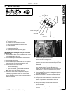
4 Water c i r culation system
Note. Fer nox Superfloc flushing solution should be used
during the flushing procedure.
a. With the system HOT examine all water connections for
tightness.
b. With the system still HOT, turn off the gas, water and
electricity supplies to the boiler and drain down, to complete
the flushing process.
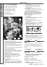
c. Refill the system, adding inhibitor (see ’Water Treatment’), if
required.
Vent as necessary to clear all air and, again, check for wat er
tightness. After venting, repressurise as required.
d. Balance t he system. It is suggested that , i nitially, all radiator
handwheel valves (or TRVs if fitted) be set fully open, that all
lockshield valves be set a half---turn open.
Make minor adjustments to each radiator to achieve the same
differential on all.
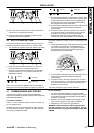
5Fluesystem
Check the integrity of the flue outlet and air inlet system to the
boiler ensuring no leaks are evident from piping joints or
flue/air sampling points .
Finally, set the system cont rols to the us ers requirements.
If an optional programmer kit is fitted refer to the instructions
supplied.
INSTALLATION