


INSTALLATION
mini HE --- Installation & Servicing
17
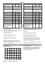
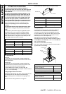
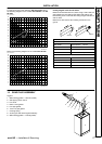
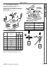
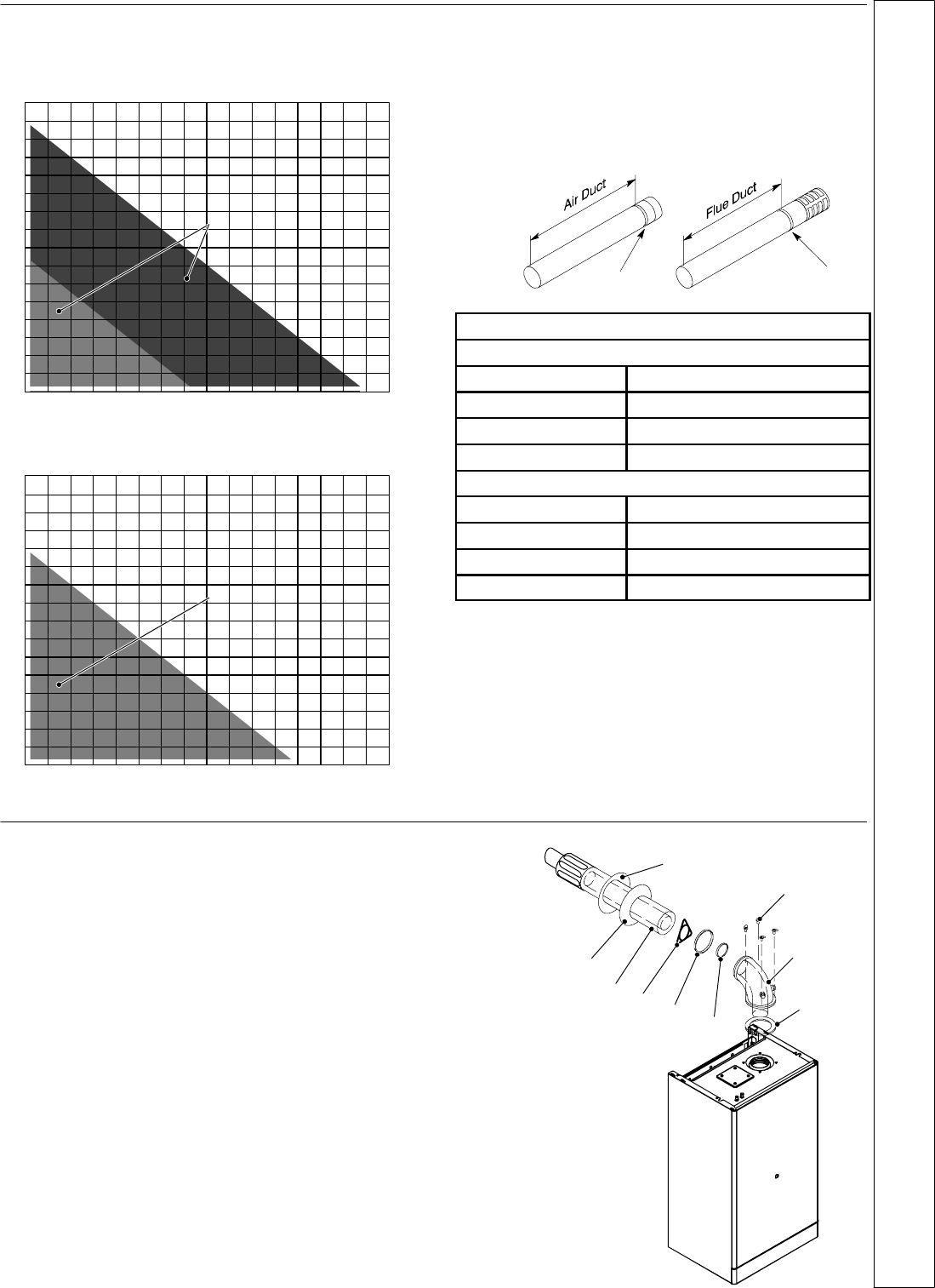
For the correct use of the restrictors with twin pipes refer to
the following diagram for the models mini HE C24,andmini
HE C28.
0
2
4
6
8
10
12
14
16
18
20
22
24
26
28
30
32
0 2 4 6 8 101214161820222426283032
Restrictor
50 mm
Allowed values
Flue exhaust ”a”
Air intake ”b”
Restrictor
55 mm
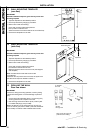
Refer to the following diagram for the model mini HE C32.
0
2
4
6
8
10
12
14
16
18
20
22
24
26
28
30
32
0 2 4 6 8 101214161820222426283032
Restrictor
50 mm
Allowed values
Flue exhaust ”a”
Air intake ”b”
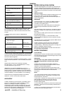
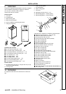
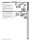
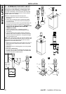
Cutting lengths of flue and air ducts
Measure the wal l thickness and, when using a side outlet, the
gap between the inner wall and the boiler side casing. Use
the following chart to calculate the cutting lengths of both flue
and air ducts.
Marktheairductandflueduct making reference on the
groove.
Groove
Groove
Twin Pipe
Air duct
Rear Outlet W all thickness + 130 mm
Rear outlet+Stand---off Wall thickness + 165 mm
Side Outlet --- RH Wall thickness + Gap + 187 mm
Side Outlet --- L H Wall thickness + Gap + 93 mm
Flue Duct
Rear Outlet W all thickness + 130 mm
Rear outlet+Stand---off Wall thickness + 165 mm
Side Outlet --- RH Wall thickness + Gap +67 mm
Side Outlet --- L H Wall thickness + Gap + 213 mm
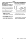
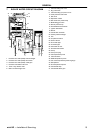
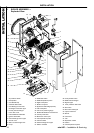
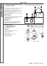
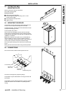
12 REAR FLUE ASSEMBLY
Legend
1 Wall finishing gasket --- external (rubber)
2 Self tapping screw 4,2x13
3 F lue turret
4 Boiler---turret gasket
5 Fluepipegasket
6 Turret---air pipe gasket
7 Centring spring
8 A ir/flue pipe with terminal grille assembly
9 Wall finishing gasket --- internal (plastic)
1
8
9
7
6
5
4
3
2
INSTALLATION