


INSTALLATION
mini HE --- Installation & Servicing
16
11 FITTING THE FLUE SYSTEM
The minimum and maximum equivalent length for
c o --- ax i a l p i p e s ø 6 0 --- 10 0 a n d ø 8 0 --- 1 2 5 m m a re g i v e n i n
Table 7 for mini HE C24 and mini HE C28 and in Table 8
for mini HE C32 .
The minimum and maximum equivalent length for ø 80
mm twin pipe systems are given in Table 9 for mini HE
C24 and mini HE C28 and in Table 10 for mini HE C32.
For roof flue systems having a flue length greater than
3m and all twin pipe systems, a co ndensate drain kit
must be fitted at the lowest point in the system. See the
list of optional extras (frame 9) for available drain kits.
Refer to the assembly instructions contained within the
chosen flue kit p ackaging for the correct assembly and
installation.
The horizontal sections of flue pipes must have a slope
not less than 1.5 deg. (25 mm per metre) towards the
boiler.
In the flue kit of pack B the flue pipe is angled within the air
duct therefore the air duct mus t be horizontally installed.
If one or more extensions need to be used they must be
adequately supported so that there is no sag in the flue pipe
and a minimum fall of 1.5 deg. (25 mm per metre) over the
whole length towards the boiler is ensured.
Table 7 mini HE C24, mini HE C28
Minimum Maximum
Co --- ax ia l 60 --- 100 0.3 (11.8”) 2.7 (8’ 10”)
Co --- ax ia l 80 --- 125 0.5 (19.7”) 8.5 (27’ 10”)
Tab le 8 m ini HE C 32
Minimum Maximum
Co --- ax ia l 60 --- 100 0.3 (11.8”) 1.8 (5’ 11”)
Co --- ax ia l 80 --- 125 0.5 (19.7”) 6.0 (19’ 8”)
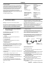
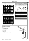
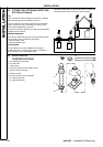
Co---axial Flue kits.
Horizontal.
For calculation of total flue length, the distance MUST be
measured from the centreline of the concentric elbow to the
end of the terminal.
Vertical outlet
For calculation of total flue length, the distance MUST be
measured from the centreline of the outlet co nnector at the
boiler top panel to the end of the terminal grille.
For each additional 45û and 90û flue bend used, the
maximum permissible length of flue system must be reduced
by1mor1,5mrespectively.
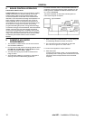
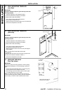
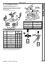
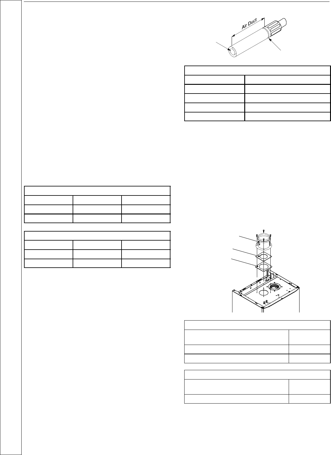
Cutting lengths of flue and air ducts
Measure the wal l thickness and, when using a side outlet, the
gapbetweentheinnerwallandtheboilersidecasing.
Use the following chart to calculate the c utting length of air
duct.
Mark the air duct making reference on the groove.
Cuttheflueductatthesameleveloftheairductedge.
Groove
Cut this end
Horizontal Concentric
Air duct
Rear Outlet W all thickness + 125 mm
Rear outlet+Stand---off Wall thickness + 160 mm
Side Outlet --- RH Wall thickness + Gap +62 mm
Side Outlet --- L H Wall thickness + Gap +208 mm
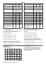
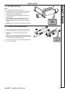
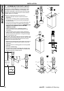
Twin pipe flue kits
For calculation of total flue length, the distance MUST be
measured from the centreline of the flue duct/air duct
connection to the end of the flue outlet grille/air inlet duc t.
For each additional 45û M&F and 90û M&F flue bend used,
themaximumpermissiblelengthoffluesystemmustbe
reduced by 0,9m or 1,65m respectively.
The restrictor to be used and the lengths of allowable
equivalent flue outl et / air inlet ducts are indicated in Table 9
for mini HE C24, mini HE C28,inTable10formini HE C32
and in the following graph.
The restrictor size is marked on its body.
N.B.: The air intake and the flue outlet must not ter minate on
opposite sides of the building.
Air intake ada pter
Restrictor
Gasket
Table 9mini HE C24, mini HE C28
Equivalent pipe length
(air duct + flue duct)
Restrictor
Between 1 (39“) and 15 m (49’ 2”) ø50mm
More than 15 m (49’ 2”) up to 30 m (98’ 5”) ø55mm
Table 10mini HE C32
Equivalent pipe length
(air duct + flue duct)
Restrictor
Between 1 (39“) and 24 m (78’ 9”) ø50mm
INSTALLATION