


84 Ceiling & Floor, Ceiling Suspended (50Hz, R22)
15. Installation
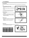
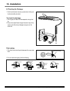
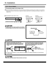
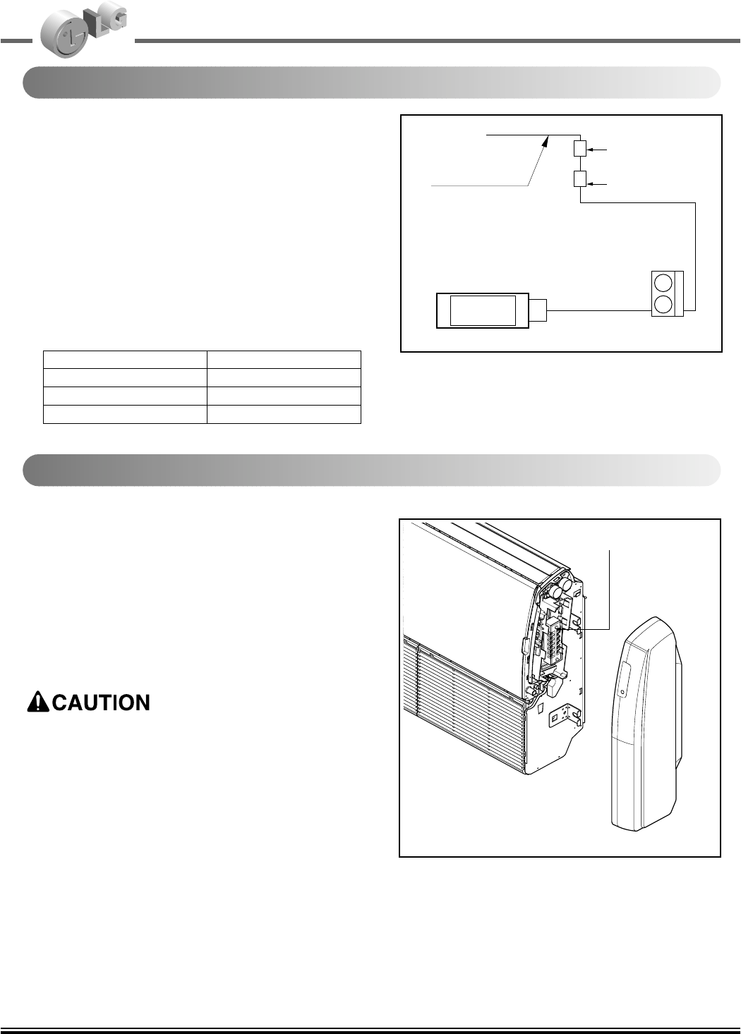
Outdoor
Indoor
Main
power source
Switch box
Circuit Breaker
Control terminal board
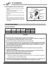
Perform the electrical wiring work according to the
electrical wiring connection.
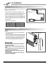
• All wiring must comply with local requirements.
• Select a power source that is capable of supply-
ing the current required by the air conditioner.
• Use a recognized circuit breaker between the
power source and the unit. A disconnection
device to adequately disconnect all supply lines
must be fitted.
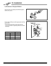
• Capacity of circuit breaker
Capacity Ampere
36kBtu/h 20A
48kBtu/h 25A
60kBtu/h 25A
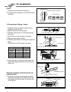
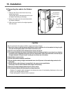
Indoor
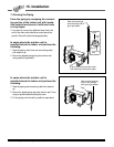
1. The control box of indoor unit is on the left side when
seen from front side.
2. Connect the cable to the indoor unit by connecting the
wires to the terminals on the control board individually
according to the outdoor unit connection (Ensure that
the color of the wires of the outdoor unit and the termi-
nal no. are same as the those of the indoor unit)
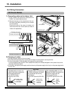
Connecting the Cables
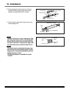
Electrical Wiring - VK/VL Chassis
• The circuit diagram behind the panel is subject to
change without notice.
• The earth wire should be longer than the common
wires.
• When installing, refer to the circuit diagram behind
the panel front of the indoor unit.
• Connect the wires firmly so that they may not be
pulled out easily.
• Connect the wires according to color codes, refer-
ring to the wiring diagram.